The three phase supply system having three different windings are placed on the armature at an angular displacement of 120 elect. Each winding has two ends or terminals, so there are six terminals taken out from the three phase alternators. These terminals are connected in different fashions.
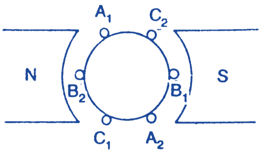
Consider three identical windings, A, B and C winding. A has two ends a1 and a2, winding B has two b1 and b2, winding C has again two c1 and c2. These are placed at 120° apart as shown in Fig. 1 (a). Let these be rotated in the magnetic field produced by a bipolar machine in anticlockwise direction with a speed equal to ω radian/sec.

(a)

(b)
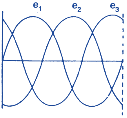
Fig. 1. Three Phase generation.
Now depending upon the Fleming’s right hand rule, there will be the production of the voltage displaced at 120° elect. apart. This e.m.f.s. are same in magnitude and frequency. These are illustrated by a sine wave as shown in Fig. 1 (b). I.et A is at 0° elect. then the e.m.f. e1 will start from zero degree, phase B from 120° apart will have a sine wave as e2 and phase C, 240° elect. apart is shown by e3. E.m.f. e2 initially is negative and approaching to negative maximum value. The e.m.f. e3 is in positive direction and decreasing to zero value as shown. These e.m.f.s. can be said as
e1 = Em sin ωt
e2 = Em sin (ωt – 120)
e3 = Em sin (ωt – 240)
Similarly the current can be drawn keeping in mind the angle of lag or lead.
INTER CONNECTIONS OF THREE PHASES
There are the following different ways of connecting these three windings for obtaining three phase supply for the load.
- Three phase six wire system.
- Delta connection or Mesh connections
- Star connection or Wye connection
Three phase six wire system
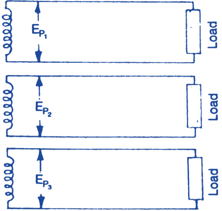
In this case the load is divided into three equal circuit and every load circuit is connected across individual circuits; as shown in Fig. 3.

Fig. 2: Three Phase Windings
Let Ep1, Ep2 and Ep3 be the phase voltages and Ip1, Ip2 and Ip3 be the currents respectively. so the power in different phase are:
Phase A = Ep1 Ip1 cos Φ Watts
Phase B = Ep2 Ip2 cos Φ Watts
Phase C = Ep3 Ip3 cos Φ Watts
In a particular machine when phase windings are identical so it will have the characteristics as given.
- The voltage across each phase is same because the windings are identical.
- In case when load is equal, the same current will flow through each phase.
The total power will now be equal to
= 3 × Phase power
= 3 × Ep Ip cos Φ.
In case of unbalanced loads, the currents i.e. Ip1, Ip2 and Ip3 are different and total power will be the sum of individual phase powers. This system is not adopted nowadays.