In this topic, you study Leakage Flux and Fringing – Definition, Diagram & Theory.
In many electromagnetic devices like generators, motors, instruments, etc., their magnetic circuits have an air path or air gap in order that the magnetic flux may be utilized to produce the desired effect. For example, in the instruments like ammeters, voltmeters, etc., the mechanical force required by the operating mechanism may be produced by keeping a piece of iron or a current carrying coil in the magnetic flux passing through the air gap. Therefore, this flux in the air gap which is actually utilized for various purposes depending upon the application is known as useful flux. Even though it is desired that all the flux produced by the magnetizing co’ should pass through the air gap where it is to be used, such an ideal condition is never achieved in actual practice. A part of the total flux always leaks out taking short paths partly through air surrounding the iron path and remote from the air gap. This is obviously because the air is not a perfect magnetic insulator. This flux which is not following the intended path for it (i.e. through the air gap) is known as leakage flux. Since the leakage flux is not passing through the air gap, it cannot be utilized for the desired purpose. Fig. 1 shows useful and leakage fluxes in the case of an iron ring with an air gap.
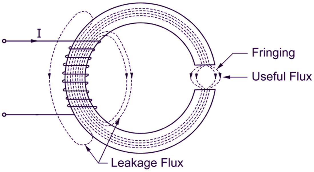
Fig. 1: Magnetic leakage and fringing
The total flux produced by the magnetizing coil is thus the sum of the useful and leakage fluxes.
The ratio of total flux to useful flux is called Hopkinson's leakage co-efficient or leakage factor.
Leakage factor (or Leakage co-efficient) is denoted by the letter λ. Thus,
\[\!\!\lambda\!\!\text{ }=\frac{\text{Total Flux}}{\text{Useful Flux}}\]
For electrical machines, the value of leakage co-efficient ranges from 1.1 to 1.25. Magnetic leakage is always undesirable for all the electrical appliances because it increases their weight and cost of manufacture. The parallel lines of force having the same sense experience mutual lateral forces of repulsion while crossing an air gap. Due to this property of lines of force, the useful flux in the air gap always has a tendency to bulge out (spread out) at the edges of the air gap as shown in Fig. 1. This effect is known as fringing. Fringing increases the effective cross-sectional area of the gap and thereby reduces the flux density in the air gap. Fringing, magnetic leakage and total reluctance of the magnetic circuit can be reduced by making the air gap as narrow as possible.