In this topic, you study Parallel Magnetic Circuit – Definition, Diagram & Theory.
When a composite magnetic circuit has two or more flux paths in parallel, it is called a parallel magnetic circuit.
In such a circuit, each path requires the same m.m.f. and the total flux divides between the paths in inverse proportion to their reluctances. For such a circuit, we always have
Total flux,
Φ = Φ1 + Φ2 + Φ3 + … + Φn
where, Φ1, Φ2, Φn, etc. are the fluxes in the individual paths.
If S1, S2, S3, etc. are the reluctances of various parallel paths of the magnetic circuit, then similar to electric circuits, the equivalent reluctance S for parallel combination is given by the relationship,
\[\frac{\text{1}}{\text{S}}=\frac{\text{1}}{{{\text{S}}_{1}}}+\frac{\text{1}}{{{\text{S}}_{2}}}+\frac{\text{1}}{{{\text{S}}_{3}}}+….+\frac{\text{1}}{{{\text{S}}_{\text{n}}}}\]
In shell type transformers and most of the electrical machines, magnetic circuits are in the form of parallel symmetrical pairs and involve series and parallel combinations of branch reluctances.

(a)

(b)
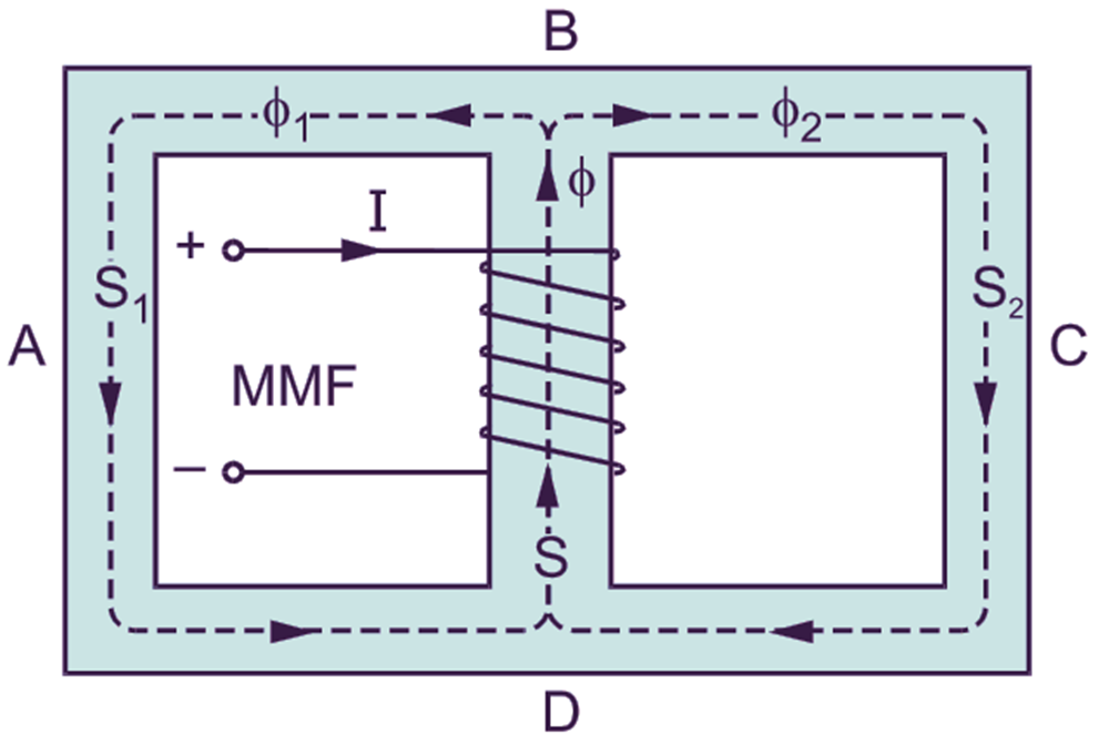
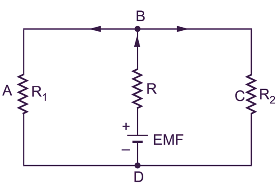
Fig. 1: (a) A series-parallel magnetic circuit, (b) Equivalent electric circuit
Fig. 1 (a) shows one such series-parallel magnetic circuit and Fig. 1 (b) its equivalent electric circuit. S, S1 and S2 are the reluctances of the paths BD, BAD and BCD respectively of the magnetic circuit and are Φ, Φ1 and Φ2 the corresponding fluxes.