In this topic, you study the definition, working, construction, types & connection diagram of phase sequence indicator.
The instrument used to determine the phase sequence of three phase supply, is known as the phase sequence indicator. This instrument indicates phase sequence of a 3 phase supply.
By “phase sequence”, we mean the order in which the phases of a supply attain their maximum value of emf. If a 3 phase supply has a phase sequence as R, Y, B, it means at first the phase R will attain its maximum value, then Y and then B will attain the maximum value of emf.
Types of Phase Sequence Indicators
They are,
- Rotatory indicators
- Static indicators.
ROTATORY PHASE SEQUENCE INDICATORS
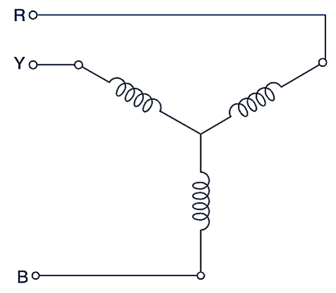
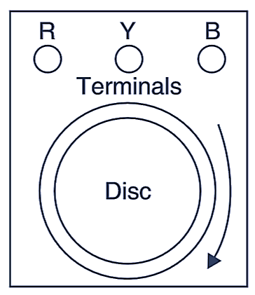
Its working principle is same as that of 3 phase induction motor. It consists of star connected three in space; displaced at 120° apart (See Fig. 1. a). The three terminals are brought out and connected to the three terminals R, Y and B of the instrument as shown in Fig. 1. (b). The coils are connected with the 3 phase supply, whose phase sequence is to be indicated. An aluminium disc is mounted on the spindle. The disc acts as a rotor and is free to rotate.
(a)
(b)
Fig. 1. Rotatory Phase Sequence Indicator.
Operation
When the three coils are connected with three phase supply, a “rotating magnetic field’ is produced which induces eddy currents in the disc. A torque acts on the disc due to motor action, thus the disc starts rotating. The direction of rotation of the disc depends upon the “phase sequence” of the supply. An arrow is marked on the disc. If direction of rotation of the disc is same as the arrow, then the phase sequence of the supply is same. If the disc rotates in the opposite direction, the phase sequence is opposite to as marked on the terminals.
STATIC PHASE SEQUENCE INDICATORS
They are of 3 types (See Fig. 2).
(a)
(b)
(c)
Fig. 2. Static Phase Sequence Indicators.
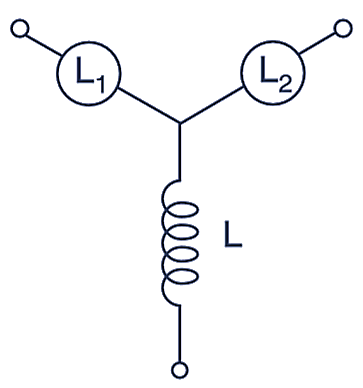
(a) It consists of two lamps L1 and L2 and an inductor L in star connection; as shown in Fig. 2 (a), When the sequence is R, Y, B, the lamp L1 glows dim and L2 glows bright. (It can be shown that voltage drop across L1 is 25
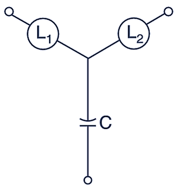
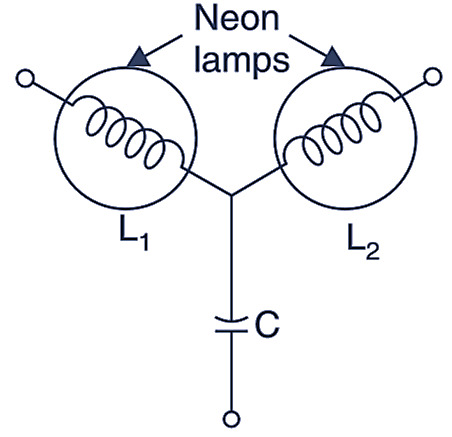
(b) If the inductor L is replaced by an equivalent capacitor C such that XL = XC. In this case if the sequence is R Y B, the lamp L1 glows bright and L2 glows dim (See Fig. 2 b) (c) In some indicators lamps L1 and L2 both are replaced by neon lamps and inductor L by a capacitor C (See Fig. 2. (c), resistors may be connected in series With the lamps to control the currents. In this case lamp L1 will glow bright and La will not glow at all i.e., will remain dark, when the sequence is R Y B, This is, because when the neon lamps are used as indicators, the lamp which has the lower voltage will not glow at all and will remain dark, as the voltage across it is lower than the “breakdown voltage” of the lamp.