In this topic, you study Scott Connection of Transformer.
A polyphase system having two or more phases can be converted into another polyphase system with any other number of phases by means of single-phase static transformers suitably interconnected. In practice, such conversion becomes essential for many practical applications. Scott connection is the most commonly used method for the conversion of three-phase system into two-phase system and vice versa. At the present time, the three-phase system being in common use, three-phase to two-phase conversion becomes essential in some special cases such as for supplying two-phase electric arc furnaces, in distribution for supplying lighting loads in rural areas, etc. Let us therefore study how this can be achieved using Scott arrangement. This method needs two identical single-phase transformers. One transformer which is usually called the main transformer has 50

(a)

(b)
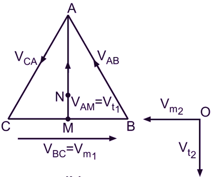
Fig. 1: (a) Scott connection, (b) Phasor diagram of voltages
Now, consider the primary of a main transformer connected between the terminals B and C of a three-phase supply. If supply line voltage is VL, then the voltage between the primary terminals B and C of the main transformer will be VL. Similarly the voltage between the primary terminals A and B or C of the transformers will also be VL. But the voltage between A and the mid-point M of the primary of the main transformer will be (√3/2) VL i.e. 0.866 VL. This can be easily verified from the phasor diagram shown in Fig. 1 (b) for the balanced three-phase voltages impressed between the terminals A, B and C of the transformers. The phasor diagram also shows that the voltages VAM and VBC are in phase quadrature. Now since the primary of a teaser transformer having 86.6
The neutral point of three-phase side, if required can be located on the teaser primary as follows. Let N be the neutral point. Then voltage of N with respect to A must be i.e. 0.578 VL. But the voltage of A with respect to M is 0.866 VL. Therefore the voltage of N with respect to M will be (0.866 VL – 0.578 VL) or 0.288 VL. Since 0.288 is one third of 0.866, the neutral point N divides the teaser primary in the ratio 1 : 2. The corresponding number of turns included between N and M will be 28.8
Current Relationship in Scott Connection of Transformer
If the secondary load currents for teaser and main transformers are It2 and Im2 respectively, then the currents on the three-phase side can be easily found from Fig. 1 (a). For that let
N2 = Number of turns on the secondary side for each transformer
N1 = Number of turns of the primary of the main transformer.
Neglecting magnetising current, the primary ampere-turns must balance the secondary ampere-turns in each transformer. Hence, Balancing current in the teaser primary,
\[{{\text{I}}_{\text{t1}}}=\frac{{{\text{N}}_{\text{2}}}}{\text{0}\text{.866 }{{\text{N}}_{\text{1}}}}\times {{\text{I}}_{\text{t2}}}\]
\[=1.16\left( \frac{{{\text{N}}_{\text{2}}}}{{{\text{N}}_{\text{1}}}} \right)\cdot {{\text{I}}_{\text{t2}}}\]
\[{{\text{I}}_{\text{t1}}}=1.16\text{ K }{{\text{I}}_{\text{t2}}}….(1)\]
where
\[\text{K}=\frac{{{\text{N}}_{\text{2}}}}{{{\text{N}}_{\text{1}}}}\]
And K is the Transformation ratio of the main transformer. Balancing current in the main transformer primary,
\[{{\text{I}}_{\text{m1}}}=\frac{{{\text{N}}_{\text{2}}}}{{{\text{N}}_{\text{1}}}}\cdot {{\text{I}}_{\text{m2}}}=\text{K}\cdot {{\text{I}}_{\text{m2}}}….(2)\]
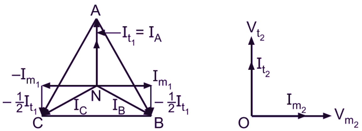
Current It1 is supplied by the phase A. Since the main transformer primary forms a return path for this current, it divides into two halves at the junction M and these component currents flow in opposite directions in the two sections of the primary winding of the main transformer. Obviously from Fig. 1 (a), the primary line currents are
\[{{\overline{\text{I}}}_{\text{A}}}={{\overline{\text{I}}}_{\text{t1}}}\]
\[{{\overline{\text{I}}}_{\text{B}}}={{\overline{\text{I}}}_{\text{m1}}}-{{\overline{\text{I}}}_{\text{t1}}}\]
\[{{\overline{\text{I}}}_{\text{C}}}=-{{\overline{\text{I}}}_{\text{m1}}}-\frac{1}{2}{{\overline{\text{I}}}_{\text{t1}}}\]
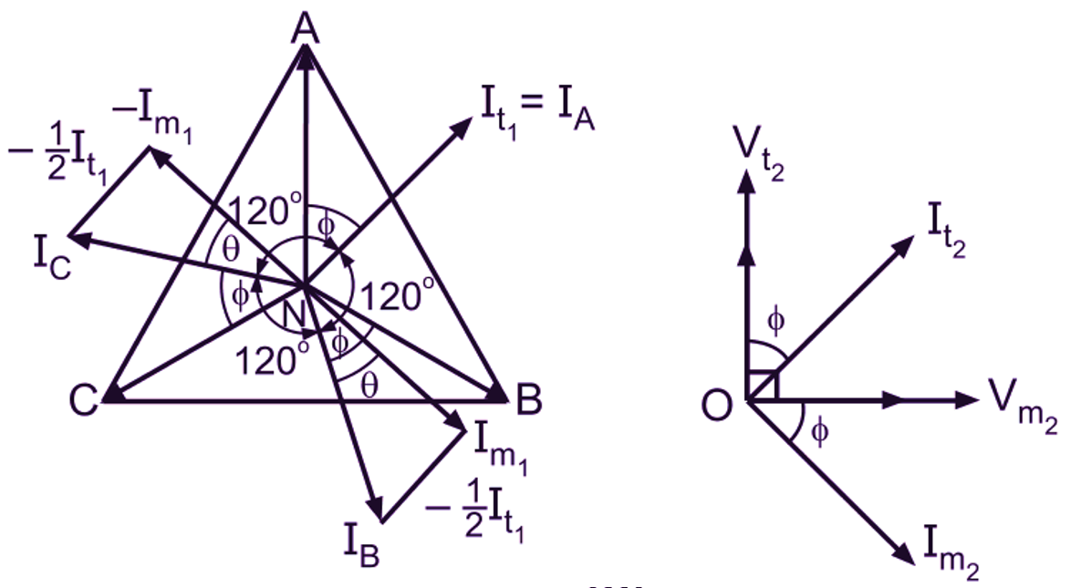
The corresponding phasor diagrams for balanced secondary side load of unity power factor and cos Φ lagging power factor are shown in Fig. 2 (a) and (b). Here, for the convenience of drawing the phasor diagrams, the corresponding voltages and currents on the primary and secondary sides of the two transformers are shown in phase and not in phase opposition as is the actual case.

(a)

(b)
Fig. 2: Scott-connection, phasor diagram for balanced load condition (a) unity power factor, (b) cos lagging power factor
From the phasor diagram of Fig. 2 (a), it is obvious that the currents drawn from the three-phase system are balanced and cophasal with the star voltages whereas in Fig. 2 (b), they are balanced but lag by Φ with respect to their respective star voltages. This can also be shown mathematically. For that let us consider the general case of balanced secondary side load of cos Φ lagging power factor. Let equal current I2 at cos Φ lagging power factor be taken from the secondaries so that
\[{{\text{I}}_{\text{t2}}}=\text{ }{{\text{I}}_{\text{m2}}}=\text{ }{{\text{I}}_{\text{2}}}\]
From the phasor diagram of Fig. 2 (b),
\[{{\text{I}}_{\text{A}}}={{\text{I}}_{\text{t1}}}….(3)\]
and,
\[{{\text{I}}_{\text{B}}}={{\text{I}}_{\text{C}}}=\sqrt{{{\text{(}{{\text{I}}_{\text{m1}}})}^{2}}+{{\text{(}\frac{1}{2}{{\text{I}}_{\text{t1}}})}^{2}}}….(4)\]
Now, in view of the equations (1) and (2), in this ease we have,
\[{{\text{I}}_{\text{t1}}}=1.16\text{ K }{{\text{I}}_{\text{t2}}}=1.16\text{ K }{{\text{I}}_{\text{2}}}\]
\[{{\text{I}}_{\text{m1}}}=\text{K }{{\text{I}}_{\text{m2}}}=\text{K }{{\text{I}}_{\text{2}}}\]
Substituting these values of Iml and It, in the equations (3) and (4), we get
\[{{\text{I}}_{\text{A}}}=1.16\text{ K }{{\text{I}}_{\text{2}}}\]
\[{{\text{I}}_{\text{B}}}={{\text{I}}_{\text{C}}}=\sqrt{{{\text{(K }{{\text{I}}_{\text{2}}})}^{2}}+{{\text{(}\frac{1}{2}\times 1.16\text{ K }{{\text{I}}_{\text{2}}})}^{2}}}\]
\[=1.16\text{ K }{{\text{I}}_{\text{2}}}\]
Thus all the line currents in the primary side am equal in magnitude. Further,
\[\tan \text{ }\!\!\theta\!\!\text{ }=\frac{(1/2){{\text{I}}_{\text{t1}}}}{{{\text{I}}_{\text{m1}}}}=\frac{0.58\text{ K }{{\text{I}}_{\text{2}}}}{\text{K }{{\text{I}}_{\text{2}}}}=0.58\]
\[\text{ }\!\!\theta\!\!\text{ }=30{}^\circ \]

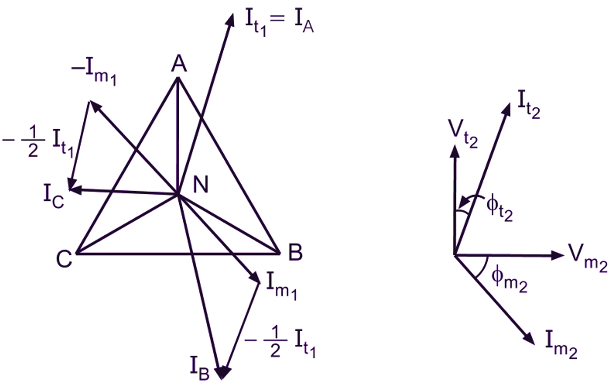
Fig. 3: Scott connection, phasor diagram for unbalanced load condition
Since the power factors of the loads on the teaser and main transformers are equal ( = cos Φ), the angle between the phasors representing secondary currents will be 90°. Therefore the angle between the phasors representing It1 and Im1, will also be 90°. Hence it will be readily seen that three line currents IA, IB and IC are displaced from each other by 120° and lag the respective star voltages by Φ. Thus it can be concluded that if the load on the two-phase side is balanced, the loading on the three-phase side also remains balanced. In the case of unbalanced loads on the secondary side (with different currents and power factors), the phasor diagram can be constructed in a similar manner. Fig. 2 shows the phasor diagram for such condition. It will be observed that if the load is unbalanced on the two-phase side, the loading on the three-phase side is also unbalanced.