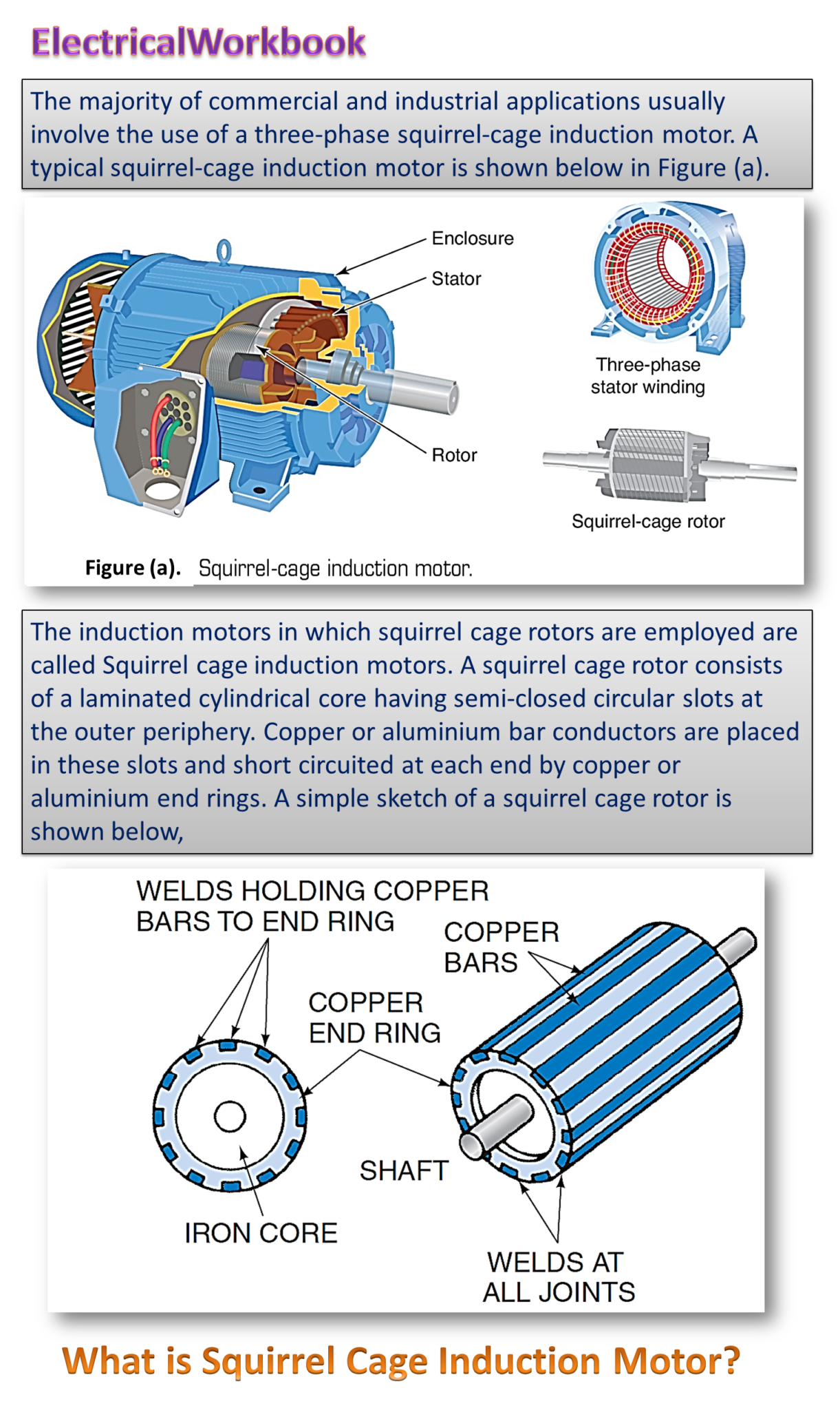
Induction motors employing squirrel cage rotor are said to be squirrel cage induction motors. As usual, the rotor core is not a solid body but consists of thin lamination with slots to carry the conductors. The rotor conductors are in the form of solid bars placed in each slot. These bars are permanently short circuited on themselves. Also to avoid magnetic Inun and reduce the possibility of rotor tooth, the bars are not kept exactly parallel to each other, rather they are given slight inclination.
Construction of Squirrel Cage Induction Motor
The stator of the squirrel cage induction motor (Fig. 1 (a)) has a laminated core provided with slots on its inner surface. The slots used may be open, semi-closed or totally closed type as illustrated in Fig. 2. A typical ring stamping (lamination) used for the stator core with open slots are also illustrated in Fig. 3 (a).
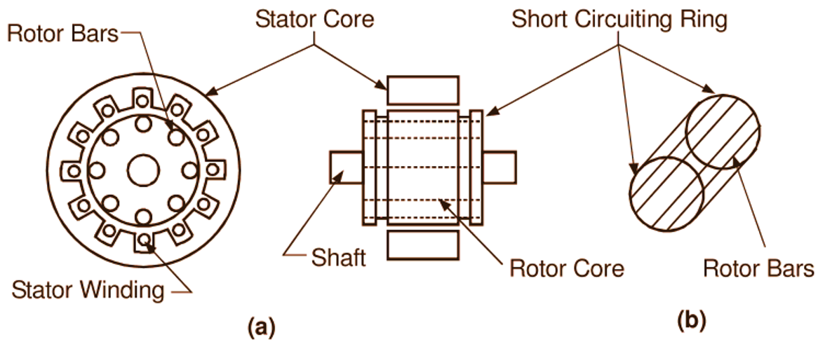
Fig. 1: (a) Induction motor with a cage rotor, (b) The squirrel cage winding
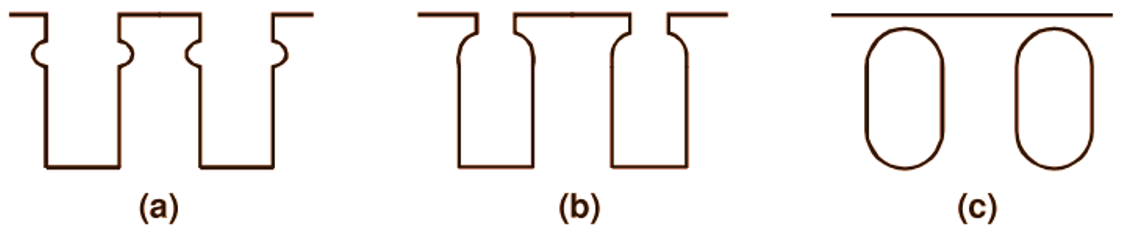
Fig. 2: Various forms of stator and rotor slots (a) Open, (b) Semi-closed, (c) Totally closed
These stampings are usually 0.4 to 0.5 mm thick and made from high grade silicon steel. They are insulated from each other by varnish or oxide coating.
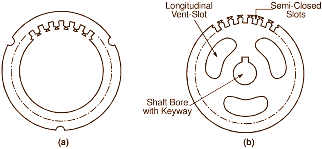
Fig. 3: Typical core laminations for (a) Stator, (b) Rotor
Such laminated construction for the core ensures low iron loss. The built-up core is fitted in either a cast or fabricated steel frame which provides the necessary mechanical protection and carries a terminal box and end covers housing the bearings. The radial ventilating ducts are provided along the length of the core with the help of spacer plates. The slotted stator core carries a three phase winding connected either in star or delta and wound for definite number of poles depending on the speed required. The rotor core also has laminated construction. In small motors, each circular lamination is of one piece (Fig. 3 (b)). The punched laminations are stacked and directly keyed to the shaft. On the other hand, in large motors, the laminations are segmented and dovetailed to a central spider. As in the stator core, ventilating ducts (both radial and axial) are also provided in the rotor core. The rotor winding of the motor consists of a series of uninsulated aluminium or copper bars, accommodated in the slots of the rotor core and permanently short-circuited at each end by a conducting ring called the end-ring. The bars are usually welded or brand to the end rings. Thus, the rotor construction resembles a squirrel cage (Fig. 1 (b)) and hence this type of rotor is called a cage rotor or squirrel cage rotor. For the motors having ratings upto about 50 kW, the entire rotor winding is often of die-cast aluminium. The aluminium bars, the end rings and even the fan blades are cast in one operation. The remarkable feature of the cage winding is that it is adaptable to any number of stator poles. This feature is important in connection with speed control. Fan blades are generally provided at the ends of the rotor core for forcing circulating air through the machine. The air gap between the stator and the rotor is kept uniform and made as small as is mechanically possible. The rotor slots are sometimes skewed (i.e. made somewhat non-parallel to the shaft) to reduce the magnetic hum (noise) and prevent possible magnetic locking (called cogging) between the Stator and rotor teeth at the time of starting. Fig. 4 shows the schematic representation of a three phase squirrel cage induction motor.
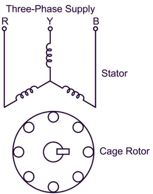
Fig. 4. Schematic representation of a 3-phase squirrel cage induction motor.
Characteristics of Squirrel Cage Induction Motor
Starting current: The starting current is about 5 to 6 times the full load current, at no load the current is less and increases with the increasing of load.
Starting torque: The starting torque of single cage rotor is less than that of the double squirrel cage induction motor. The torque increases with the increasing of load. The maximum torque is obtained at about 87
Speed: The speed at no load is nearly equal to the synchronous speed and slightly falls down with the increasing of load. The fall in speed is about 1 to 5
Power factor: The power factor is low and increases with the increasing of the load.
Applications of Squirrel Cage Induction Motor
The single cage induction motors are commonly used and are the general purpose motors. The single cage motor should not be started with load. These motors are used in lathe machine, drill machine, and other machine tools, fans etc. The double cage motor is used where high starting torque and low starting current is required, as in case of conveyors, compressors etc.
Advantages of Squirrel Cage Induction Motor
- Easy and robust construction.
- Low cost.
- No rubbing part on the rotor, so maintenance cost is less.
- Starting is easy.
Disadvantages of Squirrel Cage Induction Motor
- High starting current.
- Speed cannot be adjusted.
- Cannot be started with full load except double cage induction motor.
Why the rotor slots are slightly skewed in the squirrel cage induction motor?
Rotor slots of induction motor are skewed because of the following advantages.
- It reduces the vibration and noise of the motor.
- It restricts magnetic locking of the teeth of rotor with stator.
- It reduces the starting current and improves the starting torque.
- It minimizes the ability of air gap harmonics caused by the stator.
- It reduces slot harmonics which are generated by slots.