In this topic, you study the definition, working, construction & connection diagram of a three phase power factor meter.
The three phase power factor meter is used to find out the power factor of three phase circuits.
In case of three phase circuits the load may be balanced or the unbalanced. There can be then two possibilities that the meter for balanced load cannot measure the power factor effectively on unbalanced load. Where the power factor meter suitable for unbalanced load can measure even on balanced load.
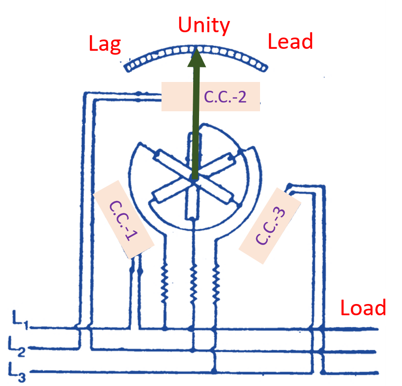
Fig. 1: Three Phase Power Factor Meter unbalance load.
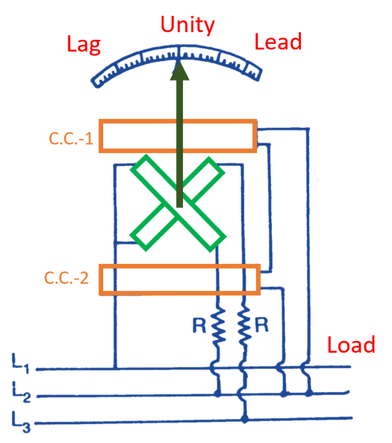
Fig. 2. Three Phase Power Factor Meter balance load.
In case of meter suitable for unbalanced load, there are three current coils and three pressure coils. The current coils are connected in series with the load. The pressure coils are connected across line, generally in star as shown in Fig. 1. Now there are two rotating magnetic fields one due to current coils and other due to pressure coils. Both will be rotating at synchronous speed. If both fields are moving in the same phase the pointer will indicate unity. Due to the angular displacement of the magnetic fields of current coil and pressure coil, the pointer will take its respective positions depending upon the capacitive and inductive components on leading or lagging side. Figs. 1 and 2 show the connection diagrams of the meter suitable for loads; whether it is unbalanced or balanced.