In this topic, you study the definition, working, construction and working of a single phase power factor meter.
The power factor of a.c. circuit plays an important role in calculating the actual work done by the supply. The power factor is defined as the ratio of real power to apparent power or the cosine of the angular displacement between current and voltage. The instrument which is used to measure power factor of a.c. single phase circuit, is known as single phase power factor meter.
Single Phase Power Factor Meter
The working principle is same as that of dynamometer type instruments.
Construction of Single Phase Power Factor Meter
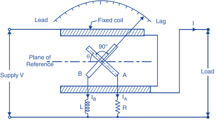
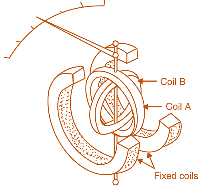
It consists of the fixed coil which is splited into two halves as shown in Fig. 1. These sets are connected in series and in series with the load. Therefore the magnetic flux produced by these coils will be proportional to the load current having the same angular displacement. There are two moving coils which are fixed on the spindle. These are placed at 90° to each other. The spindle carries the pointer. There is a calibrated scale and a pointer to indicate the reading. These moving coils are connected across the mains through inductance or capacitance and resistance as shown in Fig. 1. The value of resistance R and inductance L is so chosen that for the normal frequency in pressure coils current is same. Thus the magnetic flux produced by both the coil is maximum and spaced by 90°. Both these coils move together as these are fixed on the same spindle (Fig. 2).

Fig. 1: Single Phase Power Factor Meter.

Fig. 2: Single Phase Power Factor Meter construction.
For the measurement of power factor on the h.t. line, the meter is connected through the instrument transformers.
Working of Single Phase Power Factor Meter
The current in the current coil is same as that of the load having the same angular displacement. But current in moving coils, will depend upon the external resistance and inductances. The current in the coil having resistance will be in phase with the voltage and in inductance lagging by 90° and in case if capacitance, it will lead by 90°. Let the load is purely resistive in nature, the current and voltage in current coil will be in phase. The current in moving coil having resistance will be in phase and in other coil having capacitance will be leading by 90°. Thus the torque will be experienced on coil having resistance. Thus the pointer will indicate unity, secondly if the load in inductive the torque is mainly contributed by the coil having reactive component and the pointer will indicate to lagging side. In case of capacitive load the pointer will indicate towards the opposite direction i.e. leading side. The power factor meter have no springs for controlling torque, the controlling torque is automatically obtained because of the moving coils. Generally the scale is centre zero. The right side indicates the lagging power factor and left side the leading power factor.