In this topic, you study V/f Control of Induction Motor.
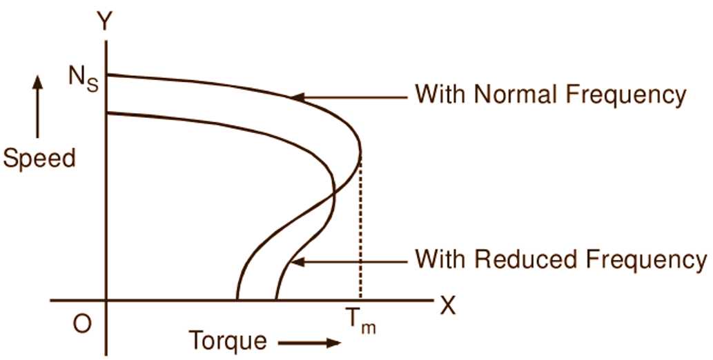
The synchronous (and therefore also running) speed of the induction motor can be varied smoothly over a wide range by changing the supply frequency. In order to maintain the air gap flux at its normal value under varying frequency conditions, it is necessary to keep E1/f and therefore V/f ratio constant. Therefore, if speed control is to be achieved by changing frequency, the supply voltage is also to be changed simultaneously to meet the above requirement. Since the commercial power systems operate at constant frequency, variation of frequency for speed control purpose is necessarily achieved by using either rotary (e.g. motor-generator sets) or solid state frequency conversion equipments. A typical frequency control scheme for induction motor using converter-inverter arrangement employing SCR circuitry is shown schematically in Fig. 1 which is self-explanatory. Fig. 2 shows typical speed-torque curves of an induction motor for two different frequencies.

Fig. 1: A typical frequency control scheme for an induction motor

Fig. 2: Speed-torque curves of an induction motor for two different frequencies
It will be observed that as the operating frequency decreases, apart from reduction in synchronous speed and consequent reduction in running speed of the motor for the given torque, the maximum torque gets reduced slightly and the starting torque increases. The large expenditure that is involved on frequency conversion equipments makes the frequency control method very expensive. Therefore, this method, so far, was very rarely used in actual practice except in few cases where independent power supplies were used e.g. in the electric propulsion of ships. But with the recent developments in semiconductor devices and reduction in their cost, frequency control method is becoming popular.