In this topic, you study Power Flow Diagram of Induction Motor.
As any other electrical motor, the induction motor also converts the electrical power supplied to it into mechanical power. Various stages of this power conversion and the accompanying losses are diagrammatically represented in Fig. 1. From this figure, it will be clear that a small part of the electrical power supplied to the motor (i.e. its stator) is utilized to supply the Stator losses consisting of Stator core and copper losses. The remaining power is transferred magnetically to the rotor through the air gap. From this rotor input power (P2), different rotor losses (rotor core and copper losses) are provided and the remaining power is converted into mechanical power (Pm). All the mechanical power developed by the rotor is not available at the shaft because part of it is always lost in supplying friction and windage losses.
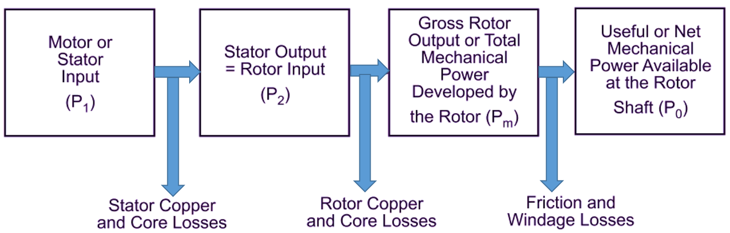
Fig. 1: Power Flow Diagram of Induction Motor