When the peak amplitude of a sinusoidal carrier is changed in proportion to instantaneous amplitude of the modulating signal, amplitude modulated wave is obtained. Fig. 1 shows the principle of amplitude modulation.
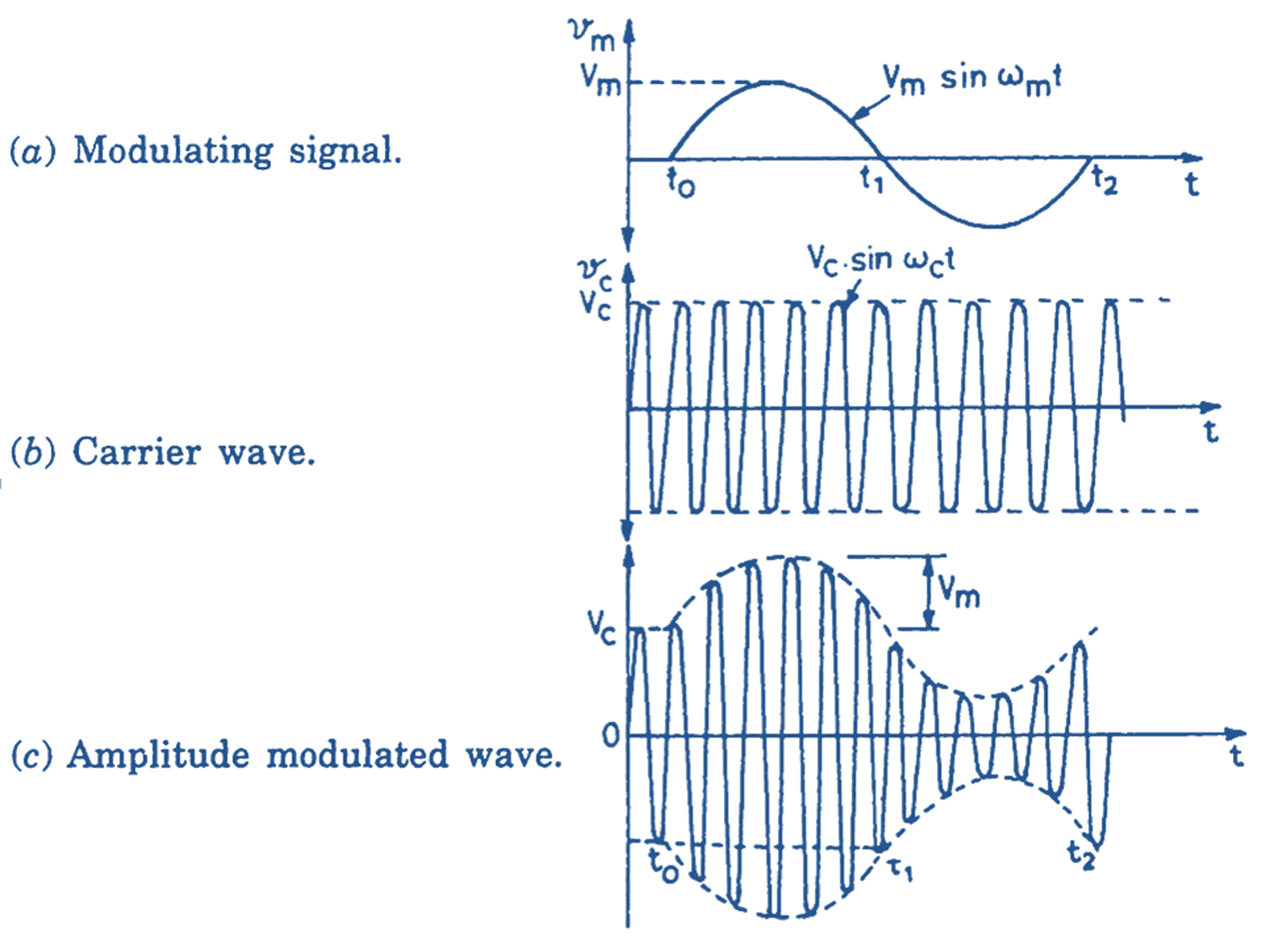
Fig. 1: Amplitude Modulation
The modulating signal as given in Fig. 1 (a) is a sinusoidal signal with peak amplitude Vm and its frequency is fm. The carrier is also a sinusoidal signal with peak amplitude VC and frequency fC as shown in Fig. 1 (b). Carrier frequency is very large to the modulating frequency.
The modulated wave is shown in Fig. 1 (c). Here the peak value of the carrier wave. (VC) is increased/decreased in proportion to the instantaneous value of the modulating signal.
Let the carrier wave be represented by the equation,
\[{{v}_{c}}={{V}_{C}}.\sin \text{ }{{\omega }_{c}}.t …(1)\]
The modulating signal is represented by
\[{{v}_{m}}={{V}_{m}}.\sin \text{ }{{\omega }_{c}}.t\]
Peak value of the modulated signal may therefore be given as,
\[{{v}_{\bmod }}={{V}_{C}}+{{V}_{m}}\sin \text{ }{{\omega }_{m}}.t\]
The instantaneous value of the modulated signal is now obtained,
\[{{v}_{\bmod }}=\left( {{V}_{C}}+{{V}_{m}}\sin \text{ }{{\omega }_{m}}.t \right)\sin \text{ }{{\omega }_{m}}.t …(2)\]
Eq. 2 gives the equation of the amplitude modulated wave. The modulated wave may be analyzed by expanding Eq. 2.
\[{{v}_{\bmod }}={{V}_{C}}\text{sin}{{\omega }_{c}}.t+{{V}_{m}}\text{sin}{{\omega }_{m}}.t\times \sin {{\omega }_{c}}.t\]
\[={{V}_{C}}\text{sin}{{\omega }_{c}}.t+\frac{{{V}_{m}}}{2}\left[ \cos \left( {{\omega }_{c}}-{{\omega }_{m}} \right)t-\cos \left( {{\omega }_{c}}+{{\omega }_{m}} \right)t \right] \]
\[={{V}_{C}}\text{sin}{{\omega }_{c}}.t+\frac{{{V}_{m}}}{2}\left[ \cos \left( {{\omega }_{c}}-{{\omega }_{m}} \right)t-\cos \left( {{\omega }_{c}}+{{\omega }_{m}} \right)t \right] \]
\[={{V}_{C}}\text{sin}{{\omega }_{c}}.t+\frac{{{V}_{m}}}{2}\cos \left( {{\omega }_{c}}-{{\omega }_{m}} \right)t-\frac{{{V}_{m}}}{2}\cos \left( {{\omega }_{c}}+{{\omega }_{m}} \right)t\]
\[={{V}_{C}}\text{sin}{{\omega }_{c}}.t+\frac{{{V}_{C}}}{2}.\frac{{{V}_{m}}}{{{V}_{C}}}\cos \left( -{{\omega }_{m}} \right)t-\frac{{{V}_{C}}}{2}.\frac{{{V}_{m}}}{2}\cos \left( {{\omega }_{c}}+{{\omega }_{m}} \right)t\]
\[={{V}_{C}}\text{sin}{{\omega }_{c}}.t+m.\frac{{{V}_{C}}}{2}\cos \left( {{\omega }_{c}}-{{\omega }_{m}} \right)t-\frac{{{V}_{C}}}{2}\cos \left( {{\omega }_{c}}+{{\omega }_{m}} \right)t …(3)\]
Where
\[m={{V}_{m\text{ }}}/\text{ }{{\text{V}}_{C}}\]
Eq. 3 shows that an amplitude wave consists of three components. The first component VC sin t has a peak amplitude VC and frequency fC. This component represents the carrier and is same as given by Eq. 1.
The second component, $\frac{m.{{V}_{C}}}{2}=\cos \left( {{\omega }_{C}}-{{\omega }_{m}} \right)t$ has a peak amplitude $\frac{m.{{V}_{C}}}{2}$ and frequency (fc – fm). Since this component has a frequency lower than the carrier frequency, it is termed as the lower side band (LSB).
The third component, $-\frac{m.{{V}_{C}}}{2}=\cos \left( {{\omega }_{C}}+{{\omega }_{m}} \right)t$ has the same amplitude $-\frac{m.{{V}_{C}}}{2}$ as the lower sideband but its phase is opposite to that of the lower side band. This component has a frequency that is higher than the carrier frequency. For this reason, this component is called the upper side band (USB). Here, ‘m’ represents the ratio of the modulating signal to the carrier signal and is called ‘modulation factor’ or ‘Depth of Modulation’ (m),
\[m=\frac{Peak\text{ }amplitude\text{ }of\text{ }the\text{ }modulating\text{ }signal}{Peak\text{ }amplitude\text{ }of\text{ }the\text{ }carrier}\]
Depth of modulation is also measured as percentage modulation. Thus when Vm = VC; m=1 and percentage modulation is 100
Frequency Spectrum in Amplitude Modulation
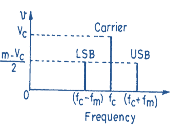
Fig. 2. Frequency spectrum of an amplitude modulated wave.
Different components of the modulated wave may be represented by plotting their magnitudes as shown in Fig. 2 which gives the frequency spectrum of amplitude modulated wave for a single modulating frequency fm. The carrier amplitude is maximum and equal to VC. The modulation does not affect the carrier but produces upper and lower side bands. These sidebands are spaced ± fm away from the carrier. The amplitude of sidebands is dependent upon the ‘depth of modulation m’. When m = 100
Drawbacks in Amplitude Modulation
Though amplitude modulation is used very widely throughout the world, it suffers from some drawbacks. A few of these drawbacks are discussed below:
(i) The amplitude modulated wave consists of the carrier, upper and lower sidebands. The carrier component does not contain any intelligence. The power in the carrier therefore goes as a waste. Since the carrier contains a signification part of the total power in the wave. If depth of modulation is 100
(ii) When a wave is radiated in free space, it encounters various electrical disturbances. These disturbances are superimposed as electrical impulses upon the modulated wave as shown in Fig. 3. Since the signal as well as noise both affect the amplitude of the carrier in the amplitude modulated wave, the receiver circuit is unable to distinguish between the modulating signal and the noise impulse and reproduces them at its output. Thus the output of an AM receiver contains signal as well as noise. Sometimes, the noise is so large that it is not possible to make out the sense of the message.
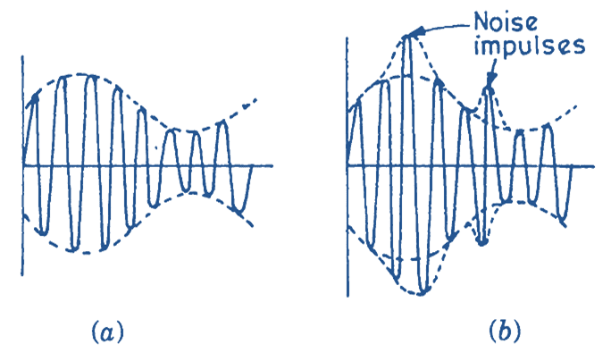
Fig. 3. Amplitude modulated wave (a) without noise and (b) with noise impulses superimposed.
(iii) The maximum permitted bandwidth in amplitude modulation is 10 kHz. Due to this limitation, the maximum frequency of the modulating signal has to be restricted to 5 kHz. Since the audio signals have a frequency range of 30 Hz to 15 kHz, signal frequencies lying above 5 kHz have to be clipped off before modulation. Due to this, quality of the signal received at the receiving end is not as good as the quality of the original programme.