This Block rotor test of Induction motor test is analogues to the short circuit test on transformer. This test gives information about copper loss of motor. The circuit diagram for this test is shown in Fig. 1.
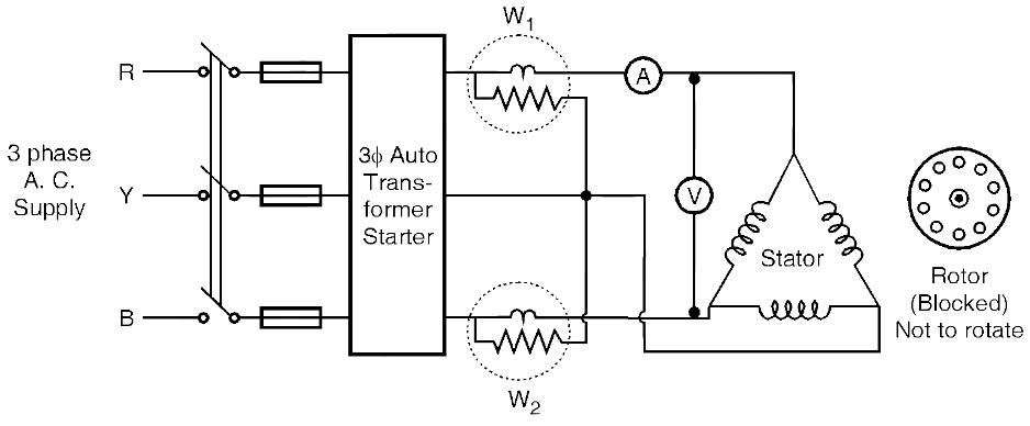
Fig. 1: Blocked rotor test of Induction motor
The rotor is held stationary or rotor is blocked i.e. it is not allowed to rotate. The stator supply voltage is gradually increased till motor carries rated or full load current. The corresponding readings are noted down. The voltage required to circulate rated current is very less (merely 5 to 8
(Volt) (Amp) (Watt) (Watt) Vsc = Voltage required to circulate rated current at short circuit condition/ blocked rotor condition Isc = rated current at short circuiting condition Wsc = Copper loss at full load Wsc = total copper loss \[{{W}_{SC}}=3I_{SC}^{2}{{R}_{01}}\] Where R01 is equivalent resistance of motor referred to stator or primary side From which \[{{R}_{01}}=\frac{{{W}_{SC}}}{3I_{SC}^{2}}\] Equivalent impedance, \[{{Z}_{01}}=\frac{{{V}_{SC}}}{{{I}_{SC}}}\] \[{{Z}_{01}}=\sqrt{R_{01}^{2}+X_{01}^{2}}\] \[{{X}_{01}}=\sqrt{Z_{01}^{2}+R_{01}^{2}}\] Thus parameters of equivalent circuit referred to stator side are calculated. Using no load an blocked rotor test efficiency of motor can be calculated as follows \[\eta =\frac{\text{Output}}{\text{Output + Iron loss + Copper loss}}\times 100\] \[\eta =\frac{\text{Output}}{\text{Output + }{{\text{W}}_{0}}\text{ + }{{\text{W}}_{\text{SC}}}}\times 100\]Observation Table of Blocked Rotor Test
Vsc
Isc
W1
W2
Wsc = W1 + W2
Calculations of Blocked Rotor Test