In this topic, you study Pole Changing Method for speed control of Induction Motor.
This method is generally used for obtaining multi-speed squirrel cage induction motor. For that, it is provided with some simple switching means for changing the number of poles on the stator winding. The basic principle of pole changing can be explained as given below.

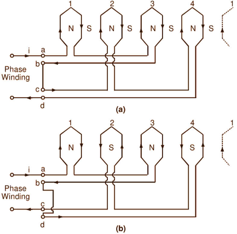
Fig. 1: Simple series connections of phase circuits for obtaining (a) 8 poles, (b) 4 poles
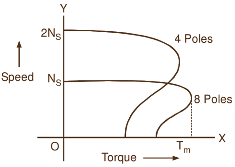
Fig. 1 (a) shows developed winding diagram for one phase of a three phase winding. Coils 1 and 3 connected in series form one coil group (or circuit) while coils 2 and 4 connected in series form another coil group. These two coil groups are connected in series in such a fashion that all four coils are magnetized in the same direction (indicated by same directions of instantaneous values of currents in these coils in the diagram). Hence, these coils form four North poles. Four consequent poles of opposite polarity i.e. South poles are produced midway between the coils. Thus, this arrangement gives total eight poles. But if the two coil groups am connected in series as shown in Fig. 1 (b), there will be in all four poles only. Obviously, the synchronous speed in this case will be double of that in the first case. The corresponding speed-torque curves are shown in Fig. 2. Two-speed motors with the speed ratios other than 1 : 2 are obtained by the use of two separate motor windings. By a combination of two stator windings, each with the provision of pole changing, a four-speed motor may be obtained.

Fig. 2: Typical speed-torque curves of a pole changing induction motor
This method of speed control is more suitable for squirrel cage induction motors rather than slip-ring induction motors. This is because a cage type rotor is adaptable to any number of stator poles. But this is not the case with a wound rotor. To avoid negative torque development by some rotor conductor belts, a slip-ring induction motor requires a pole changing arrangement on the stator as well as on the rotor.