In this topic, you study Slip in Induction Motor.
In an induction motor, it is impossible for the rotor to run at synchronous speed. If it runs at synchronous speed, there will be no relative motion between the rotating magnetic field produced by the stator and the rotor conductors. As a result, there will be no induced emf and no current in the rotor conductors. Therefore, no torque will be produced. Actually, the speed of the motor adjusts itself so that the magnitude of the rotor current is just sufficient to produce a torque equal to that required by the rotor losses and the load if any on the motor. For example at no load, the retarding torque is only due to the mechanical (friction and windage) and other no-load losses. Therefore, the speed very nearly reaches synchronous value. On the application of a load, the speed falls. Thereby the rotor emf and the current are increased. Thus the motor meets the increased demand for the torque. The speed of the rotor relative to that of the rotating magnetic field produced by the stator is known as absolute sup or only sup (or sometimes, slip speed. In other words, slip is the difference between the synchronous speed (Ns) and the actual speed (N) of the rotor. It is usually expressed as a fraction or percentage of the synchronous speed. Thus Fractional slip,
\[\text{S}=\frac{{{\text{N}}_{\text{S}}}-\text{N}}{{{\text{N}}_{\text{S}}}}…(1)\]
And percentage slip,
\[\text{S}=\frac{{{\text{N}}_{\text{S}}}-\text{N}}{{{\text{N}}_{\text{S}}}}\times 100\]
Rearranging the Equation (1), we get
\[\text{N = }{{\text{N}}_{\text{S}}}(1-\text{S})\]
At starting, N = 0. Therefore, value of the slip is 1. The value of the full-load slip is about 4 to 5
Measurement of Slip of Induction Motor
Some most commonly used methods of measuring slip of an induction motor are as follows
By Actual Measurement of Motor Speed
In this method, the motor speed is actually measured with the help of a tachometer. Slip is then calculated from the knowledge of the synchronous speed of the machine using the equation,
\[\text{S}=\frac{{{\text{N}}_{\text{S}}}-\text{N}}{{{\text{N}}_{\text{S}}}}\]
By Measurement of Rotor Frequency
Since the rotor frequency is very low, it can be accurately measured with the help of a centre-zero type dc moving-coil millivoltmeter (or galvanometer) inserted in the rotor circuit. Fig. 1 (a) illustrates the method of connecting a millivoltmeter along with its protective resistance across the slip-rings of slip-ring induction motor. In the case of squirrel-cage induction motor, it is possible to pick up inductively some voltage of rotor frequency by connecting a millivoltmeter with its protective resistance across the ends of the motor shaft as illustrated in Fig. 1 (b) or by connecting it across a large flat search coil of many turns placed centrally against the end plate on the non-driving end of the motor. Rotor frequency is determined by counting the number of complete oscillations made by the pointer of millivoltmeter about its mean zero position per second. Slip is then found by using the relationship between supply frequency and rotor frequency as follows :
\[\text{S = }\frac{\text{Rotor frequency}}{\text{Supply frequency}}\]
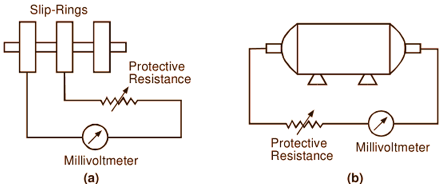
Fig. 1.25: Measurement of slip of an induction motor by measuring rotor frequency (a) Slip-ring induction motor, (b) Squirrel-cage induction motor.
Stroboscopic Method
In this method, a disc painted with alternate black and white sectors are attached to the end of the motor shaft as shown in Fig. 2. The number of black sectors as well as white sectors on the disc are each equal to the number of motor poles. The disc is illuminated by a neon lamp connected across the leads of the motor either directly or through a transformer. Such a lamp has the typical characteristic that it glows twice in a cycle when the voltage is above certain limit. If the speed of the motor were synchronous, each sector on the disc would move forward a pole pitch in a period of half cycle. Hence, one black sector seen by the observer at the instant of first maximum illumination from the lamp would advance to the position of the next black sector, at the instant of next maximum illumination.
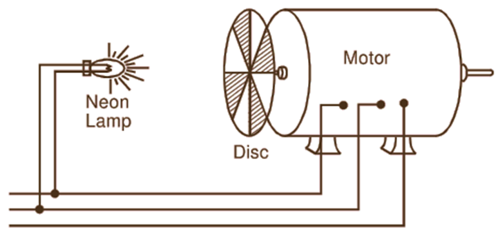
Fig. 2: Stroboscopic method of measuring slip of an induction motor
The same thing would happen in the case of each white sector. Thus in effect, the disc would appear to be stationary. But when there is a slip, each sector in the above situation will fail to reach the position of the next adjacent sector of the same colour. So the disc will not appear to be stationary but will seem to be rotating slowly backward. The speed in r.p.m. with which the disc appears to rotate backward gives the slip-speed of the motor. The slip may then be found from the relation,
\[\text{S}=\frac{{{\text{N}}_{\text{S}}}-\text{N}}{{{\text{N}}_{\text{S}}}}\]
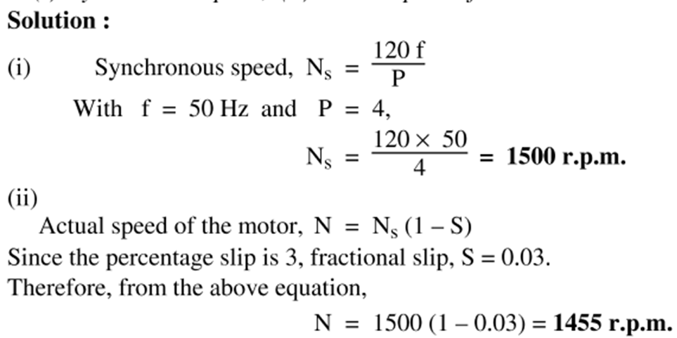
Solved problems on Slip Induction Motor
Example 1
A 3-phase. 4-pole, 50 Hz induction motor works a full load slip of 3