In this topic, you study Rotor Resistance Control of Induction Motor.
For an induction motor working at or near full-load slip, the torque and slip are related approximately as
\[\text{T}\propto \frac{\text{S}}{{{\text{R}}_{\text{2}}}}\]
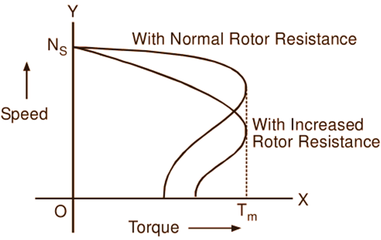
For a given torque, therefore, the slip at which the motor works is proportional to the rotor resistance. Using this fact, in the case of slip-ring induction motors, the slip can be artificially increased and hence the speed can be decreased by introducing the external resistance in series with each phase of the rotor winding. By this method, any speed below the normal value down to the crawling can be obtained. Fig. 1 shows the typical speed-torque curves of a slip-ring induction motor using rotor resistance control. The rotor-resistance starter if continuously rated may be used for the speed control purposes.

Fig. 1: Speed-torque curves of an induction motor with rotor-resistance control.
Drawbacks of Rotor Resistance Control
Even though this method of speed control is simple, it has following drawbacks :
- This method can be applied for only slip-ring induction motor.
- It cannot give speeds above normal.
- Reduction in speed is at the cost of efficiency.
- With a large resistance in the rotor circuit, the speed regulation of the motor is very poor i.e. a small change in load produces a large change in speed. Hence the motor under this condition acts almost as a variable-speed drive.
- Due to cooling arrangement needed, the resistance controllers i.e. external rotor resistors are comparatively bulky and expensive.
Because of the above limitations, this method is used only in those cases where motors are to be started against heavy loads and where speed control is needed for short periods or the reduction is only a few percent of normal speed.