In this topic, you study Three Phase Induction Motor.
Three Phase Induction Motor (Fig. 1) consists of a set of three phase windings distributed in slots around the stationary outer member called stator. The rotating member which is known as rotor also carries the other set of windings. When the stator windings are connected to the three phase conductor of the rotor experiences a mechanical force which ultimately results into rotation of the rotor. The rotating field due to stator currents and the rotor currents react to produce force on the rotor conductors and the torque.
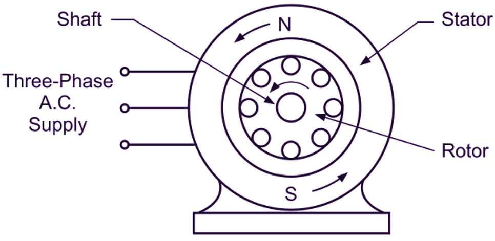
Fig. 1: Three Phase Induction Motor
To understand this more clearly, assume that the stator field is rotating in an anticlockwise direction and the rotor is stationary as illustrated in Fig. 2 (a). The relative motion of the rotor, with respect to the stator field is then obviously in the clockwise direction (Fig. 2 b). in other words, this means that if the field is ¡s made stationary. the rotor can be assumed to be rotating in the clockwise direction. Under this condition, the direction of the induced emf in the rotor conductor shown in the figure. as given by Fleming’s right-hand rule is in the plane of the paper. The current set up by this induced emf is also in the same direction. Fig. 2 (b) also shows the direction of the flux due to the rotor current alone and the resultant flux pattern is shown in Fig. 2 (c). The stretched flux lines exert the force on the rotor conductor due to which the rotor rotates in the anticlockwise direction. Thus the rotor rotates in the same direction as that of the stator flux.
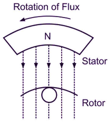
(a)
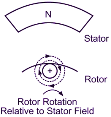
(b)
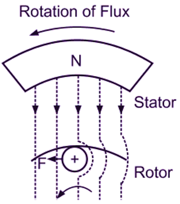
(c)
Fig. 2: Production of torque in a three phase induction motor
This can be explained in another way also. According to Lenz’s law, the direction of the induced current in the rotor conductors is always such as to oppose the very cause producing it. In this case, the cause producing the current in the rotor conductors being the relative speed between the rotating flux of the stator and the stationary rotor conductors, the rotor starts rotating in the same direction as that of the flux to reduce the relative speed between them. It should be noted that no electrical connection exists between the two sets of windings, on the stator and the rotor. Thus the motor purely works on the induction principle.
Types of Three Phase Induction Motors
A three phase induction motor consists essentially of two main parts, namely a stator and a rotor. Depending on the type of rotor used, there are two principal varieties available of the three phase induction motor.
- Squirrel cage Induction Motors
- Slip-Ring or Wound-Rotor Induction Motors
Synchronous Speed in Three Phase Induction Motor
The speed of the rotating magnetic field produced by the stator winding of the three phase induction motor depends upon the supply frequency (f) and the number of poles (P) for which the motor is wound. The relation among speed (N), frequency and number of poles is given by the expression.
\[\text{N}=\frac{\text{120f}}{\text{P}}\text{ r}\text{.p}\text{.m}\text{.}\]
This speed of rotating magnetic fleld is known as the synchronous speed of the motor and denoted by NS. Thus,
\[{{\text{N}}_{\text{S}}}=\frac{\text{120f}}{\text{P}}\text{ r}\text{.p}\text{.m}\text{.}\]