In this topic, you study Series Magnetic Circuit – Definition, Diagram & Theory.
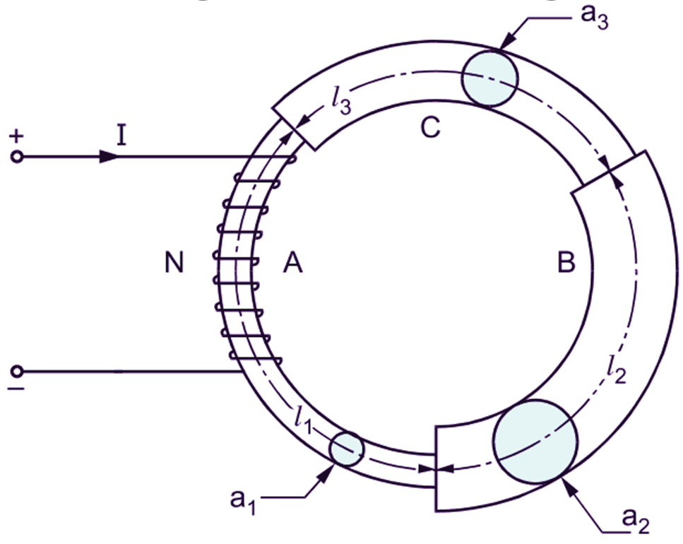
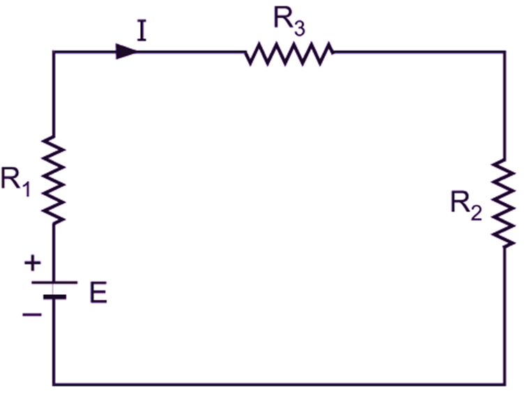
In practice, a magnetic circuit may consist of several parts of different magnetic materials with different lengths, cross-sectional areas and permeabilities. Such a circuit is known as composite magnetic circuit. In a composite magnetic circuit, when the various parts are connected one after the other in such a way that they form a chain, it is called a series magnetic circuit. Naturally, upon providing the magnetomotive force, the same flux is established through each part of a series magnetic circuit. Fig. 1 (a) shows a series magnetic circuit consisting of three parts A, B and C of different magnetic materials and Fig. 1 (b) shows the equivalent electric circuit.

(a)

(b)
Fig. 1: (a) Series magnetic circuit, (b) Equivalent electric circuit
Let l1, l2 and l3 be the lengths, a1, a2 and a3 be the cross-sectional areas and μr1, μr2 and μr3 be the relative permeabilities of the parts A, B and C respectively. If S1, S2 and S3 are the reluctances of these three parts, then
\[{{\text{S}}_{1}}=\frac{{{l}_{1}}}{\text{ }{{\mu }_{\text{o}}}\text{ }{{\mu }_{\text{r1}}}\text{ }{{\text{a}}_{1}}}\]
\[{{\text{S}}_{2}}=\frac{{{l}_{2}}}{\text{ }{{\mu }_{\text{o}}}\text{ }{{\mu }_{\text{r2}}}\text{ }{{\text{a}}_{2}}}\]
\[{{\text{S}}_{3}}=\frac{{{l}_{3}}}{\text{ }{{\mu }_{\text{o}}}\text{ }{{\mu }_{\text{r3}}}\text{ }{{\text{a}}_{3}}}\]
Let the flux passing in the different components of the magnetic circuit be Φ webers when the magnetomotive force (F) is supplied by the coil of N turns carrying the current of I amperes as shown. If F1, F2 and F3 are the m.m.fs for the three parts, then obviously,
Total M.M.F = F1 + F2 + F3
Since,
\[\text{Flux}=\frac{\text{M}\text{.M}\text{.F}\text{.}}{\text{Reluctance}}\]
\[\text{Total M}\text{.M}\text{.F}=\text{ }\phi \text{ }{{\text{S}}_{1}}+\text{ }\phi \text{ }{{\text{S}}_{2}}+\text{ }\phi \text{ }{{\text{S}}_{3}}\]
But,
$\text{F = }\phi \text{ S}$
where S is the equivalent of the three reluctances in series. Hence,
\[\phi \text{ S}~=\phi \text{ }{{\text{S}}_{1}}+\text{ }\phi \text{ }{{\text{S}}_{2}}+\text{ }\phi \text{ }{{\text{S}}_{3}}\]
Dividing each term by Φ we get,
\[\text{S}~={{\text{S}}_{1}}+\text{ }{{\text{S}}_{2}}+\text{ }{{\text{S}}_{3}}\]
Or, substituting values of S1, S2 and S3
\[\text{S}=\frac{{{l}_{1}}}{\text{ }{{\mu }_{\text{o}}}\text{ }{{\mu }_{\text{r1}}}\text{ }{{\text{a}}_{1}}}+\frac{{{l}_{2}}}{\text{ }{{\mu }_{\text{o}}}\text{ }{{\mu }_{\text{r2}}}\text{ }{{\text{a}}_{2}}}\]
\[+\frac{{{l}_{3}}}{\text{ }{{\mu }_{\text{o}}}\text{ }{{\mu }_{\text{r3}}}\text{ }{{\text{a}}_{3}}}\]
From the various results obtained above, it will be readily seen that these results are much on the same lines as the corresponding results for the series electric circuit. They can be summarized as below:
(i) The same flux (Φ) is established through each part.
(ii) The total m.m.f. (F) is equal to the sum of the individual m.m.fs for the various parts i.e.
\[\text{F}\left( \text{given by N}\text{.I} \right)\text{ = }{{\text{F}}_{\text{1}}}\text{+ }{{\text{F}}_{\text{2}}}\text{+ }{{\text{F}}_{\text{3}}}\text{+ }….\text{+ }{{\text{F}}_{\text{n}}}\]
(iii) The equivalent reuctance of number of reluctances joined in series is equal to the sum of the values of the individual reluctances i.e.
\[\text{S = }{{\text{S}}_{\text{1}}}\text{+ }{{\text{S}}_{\text{2}}}\text{+ }{{\text{S}}_{\text{3}}}\text{+ }{{….}_{\text{ }\!\!~\!\!\text{ }}}\text{+ }{{\text{S}}_{\text{n}}}\]
Computation of Total M.M.F. for Series Magnetic Circuits
We know that in any magnetic circuit, following relation exists between flux, m.m.f. and reluctance.
\[\text{Flux}=\frac{\text{M}\text{.M}\text{.F}\text{.}}{\text{Reluctance}}\]
Therefore, the general expression for total magnetomotive force (given by N.I necessary to establish a flux in a series magnetic circuit similar to that considered in Fig. 1 (a), can be stated as follows:
\[\text{Total M}\text{.M}\text{.F}\text{. = Flux }\!\!~\!\!\text{ }\!\!\times\!\!\text{ Reluctance}\]
\[\text{= }\phi \text{ S}\]
\[\text{= }\phi \text{ }\left( {{\text{S}}_{\text{1}}}\text{+ }{{\text{S}}_{\text{2}}}\text{+ }{{\text{S}}_{\text{3}}} \right)\]
Substituting the values of S1, S2 and S3, this expression can be further modified as
$\text{Total M}\text{.M}\text{.F}\text{.}$
\[=\phi \left( \frac{{{l}_{1}}}{\text{ }{{\mu }_{\text{o}}}\text{ }{{\mu }_{\text{r1}}}\text{ }{{\text{a}}_{1}}}+\frac{{{l}_{2}}}{\text{ }{{\mu }_{\text{o}}}\text{ }{{\mu }_{\text{r2}}}\text{ }{{\text{a}}_{2}}}+\frac{{{l}_{3}}}{\text{ }{{\mu }_{\text{o}}}\text{ }{{\mu }_{\text{r3}}}\text{ }{{\text{a}}_{3}}} \right)\]
Since,
\[=\frac{{{\text{B}}_{1}}}{\text{ }{{\mu }_{\text{o}}}\text{ }{{\mu }_{\text{r1}}}\text{ }{{\text{a}}_{1}}}\times {{l}_{1}}+\frac{{{\text{B}}_{2}}}{\text{ }{{\mu }_{\text{o}}}\text{ }{{\mu }_{\text{r2}}}\text{ }{{\text{a}}_{2}}}\times {{l}_{2}}\]
\[+\frac{{{\text{B}}_{3}}}{\text{ }{{\mu }_{\text{o}}}\text{ }{{\mu }_{\text{r3}}}\text{ }{{\text{a}}_{3}}}\times {{l}_{3}}\text{ }….(1)\]
Since,
\[\text{H}=\frac{\text{B}}{\text{ }{{\mu }_{\text{o}}}\text{ }{{\mu }_{\text{r}}}}\]
\[\text{Total M}\text{.M}\text{.F}\text{. = }{{\text{H}}_{1}}{{l}_{1}}+{{\text{H}}_{2}}{{l}_{2}}+{{\text{H}}_{3}}{{l}_{3}}…(2)\]
where B1, B2 and B3 are the flux densities and H1, H2 and H3 are the corresponding magnetic field strengths in the three parts A, B and C respectively. Thus, if the B-H curves for the different materials are available, then after reading the values of H corresponding to the various flux densities from these curves, the total magnetomotive force can be easily calculated using the Expression (2). This method of magnetic calculations is of more practical importance in comparison with that using reluctance (refer to the Equation 1).The usual steps followed to find the total m.m.f for a series magnetic circuit are as follows:
(i) Find the magnetic field strength (H) for each part of the circuit using the relation
\[\text{H}=\frac{\text{B}}{\text{ }{{\mu }_{\text{o}}}\text{ }{{\mu }_{\text{r}}}}\]
or from the B-H curve for the magnetic material.
(ii) Calculate the m.m.f. for each part by using the expression,
\[\text{M}\text{.M}\text{.F}\text{. = H}\times l\]
(iii) Finally, calculate the total m.m.f. for the entire magnetic circuit by adding m.m.fs for the various parts. Thus,
\[\text{Total M}\text{.M}\text{.F}\text{. = }{{\text{H}}_{1}}{{l}_{1}}+{{\text{H}}_{2}}{{l}_{2}}+{{\text{H}}_{3}}{{l}_{3}}+..\]
\[..+{{\text{H}}_{\text{n}}}{{l}_{\text{n}}}\]