In this topic, you study Wave Winding – Definition, Theory, & Diagram.
In wave winding, coils are connected in series. The finish of first coil is connected to the start of the second coil placed at a distance of two pole pitches away (see Figure 1).
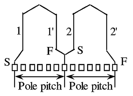
Figure 1: Wave Winding.
The winding progresses in the same way for the next coils till it comes back to the starting slot. Therefore, irrespective of the number of poles there are two parallel paths between the negative and the positive terminals of the armature. Terminals of wave wound generator can supply more voltage than the lap wound generator. A lap wound generator can give more current than the wave wound generator.
In this type of winding, the two ends of each armature coil are bent in opposite directions and these ends are then connected to those commutator segments which are nearly two pole-pitches apart. Fig. 2 shows single and multi-turn coils used in the wave winding and Fig. 3 (a) shows the developed view of a part of simple wave winding using single-turn coils. Since the winding advances from pole to pole in the same direction round the armature in a manner similar to that of a wave, it is called the wave winding.
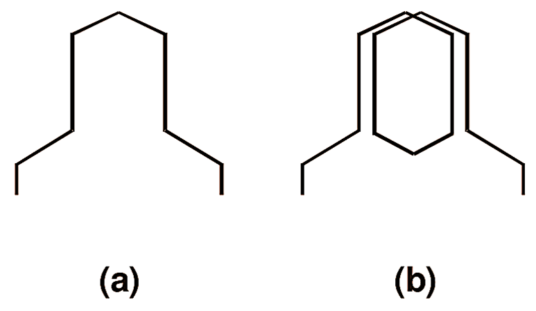
Fig. 2: (a) Single-turn coil, wave winding, (b) Multi-turn coil, wave winding.
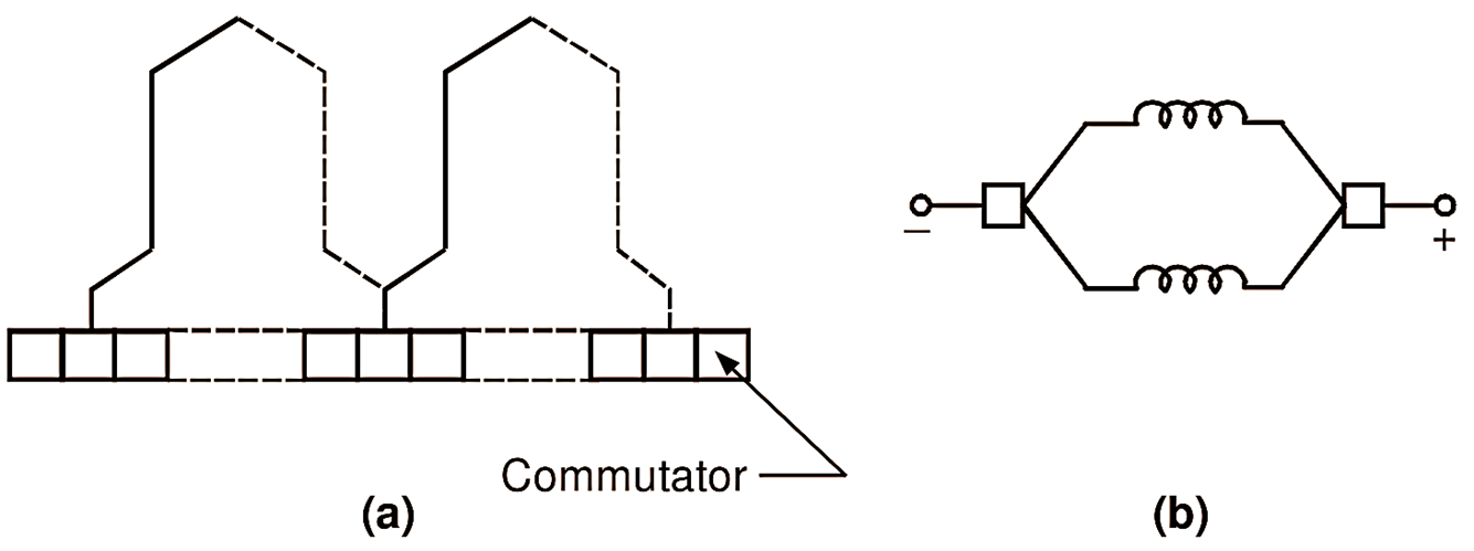
Fig. 3: (a) Developed view of a part of simple wave winding, (b) Equivalent circuit, wave winding.
General Characteristic Features of Wave Winding
Some of the important characteristic features of the wave winding are as follows
- Only two brushes are necessary, although as many brushes as number of poles are frequently employed for lowering current carried per brush. This decreases the size of the brushes and reduces the length of the commutator. The number of parallel paths between the positive and negative brushes is always two, regardless of the number of poles. Because of this characteristic of tile wave winding, it is also called two circuit or series winding. Fig. 3 (b) shows the equivalent circuit for the wave winding.
- The total e.m.f. of the machine is equal to the e.m.f. generated in any one of the parallel paths.
- Each parallel path supplies half of the total current output.
Dummy Coils in Wave Windings
The wave winding is possible only with a particular number of coil sides. Sometimes, standard stampings with a definite number of slots are only available. 1f the armature cores made up of such stampings are to be used with the required number of coil sides for the wave winding, some of the slots will have to be kept without any coil sides. This will lead to mechanical imbalance of the armature. Therefore, instead of keeping some slots empty, more coils (usually one more) are provided than the required number and left without any connections to the commutator segments. These extra coils obviously do not contribute to the induced e.m.f. in the armature and arc, therefore, known as dummy coils. However, the use of such dummy coils is generally avoided because of the dissymmetry they introduce. Such dummy coils are not needed for lap windings.