In this topic, you study Armature Winding – Definition, Theory, Diagram & Types.
The armature windings are the conductor coils placed in the slots of magnetic core mounted on the shaft of the rotor of a D.C machine . The pictorial view of armature winding shown in Figure 1.
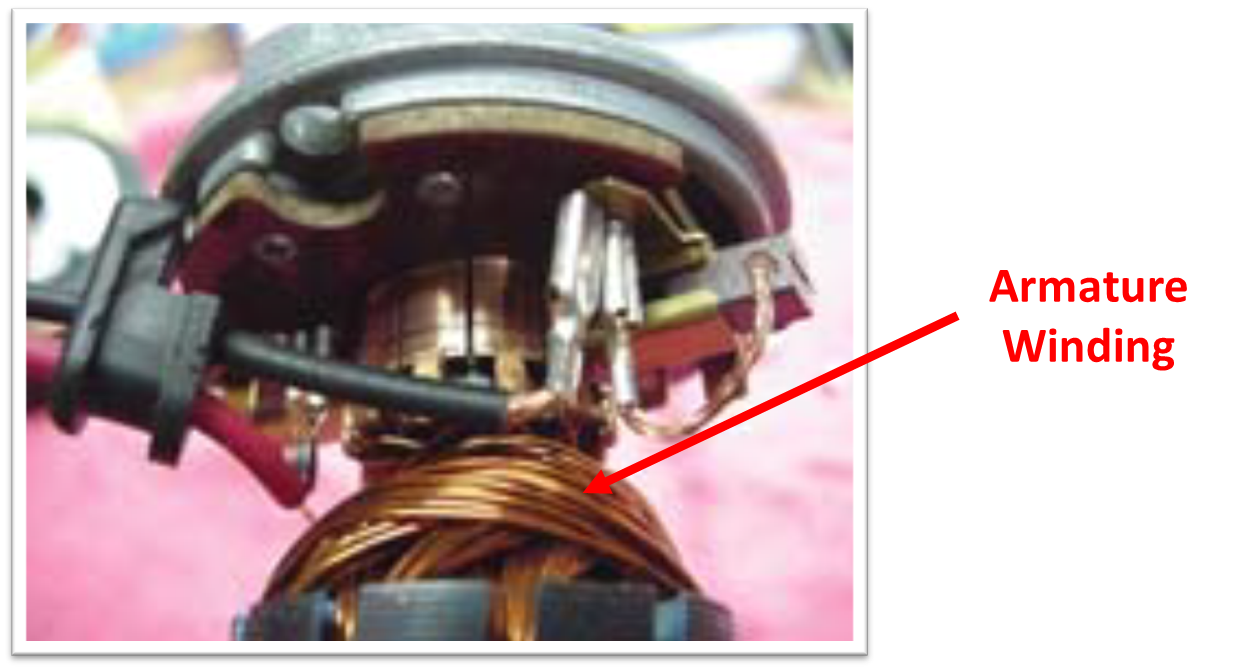
Figure 1: Armature Winding.
As the e.m.f induced for one turn is very small, the winding is a coil consisting of many turns to get the required e.m.f. The coils with many turns are diamond shaped as shown in figure (1), with start and finish ends.
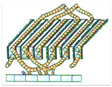
Figure 2.
These ends are terminated on commutator segments. The diamond shape positions are, one side of a coil in the upper half of a slot and the other side of a coil in the lower half of another slot. Similarly, it is vice versa for another coil in the same slots. This is a double layered winding arrangement generally used on any D.C machine. A coil rotated in a magnetic field induces current. The current is in the same direction in both sides of the coil. Hence, during rotation when one side of the coil comes under north pole, the other side of the coil comes under south pole. The displacement between the sides of the coil is called the coil span. It is one pole pitch. There are two types of armature windings as follows,
- Lap winding
- Wave winding
Armature Winding Commonly Used Terms
Conductor: It is the active length (part actually lying in the magnetic Field and in which an e.m.f. is induced) of wire or strip embedded in the slot on the armature periphery (see Figure 3).
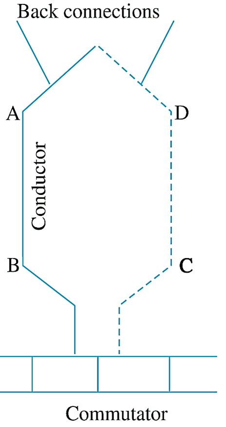
Fig. 3: Armature windingSingle-turn coil.
Turn: Every two conductors laid in a pair of slots and connected to each other form one turn (see Figure 3).
Coil: A coil may consist of a single turn or may consist of many turns connected in series. A coil with one turn is called a single-turn coil while a coil with more than one turn is known as multi-turn coil. (Fig. 4 and Fig. 5).
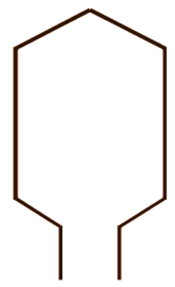
Fig. 4: Single-turn coil
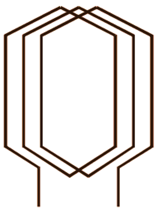
Fig. 5: Multi-turn coil
Pole-Pitch: The pole-pitch is the centre to centre distance (over the armature periphery) between two adjacent poles. It is usually expressed in terms of slots per pole or coil sides per pole. e.g. if there are 24 slots, 24 coils, and 4 poles, then pole-pitch is
\[\frac{24}{4}=\text{ }6\text{ slots or }\frac{24\times 2}{4}=12\text{ coil sides}\]
Coil Span: It is the distance on the periphery of the armature spanned by the two sides of the coil. It is usually expressed in terms of corresponding armature slots (or coil sides). If the coil span is exactly equal to the pole-pitch, then such a coil is called a full-pitch coil. On the other hand, if its span is less than a pole-pitch. it is said to the a fractional-pitch coil. Alternatively, this type of coil is also called a short-pitch or chorded coil. For example, in a 6-pole armature having 96 slots, a coil spanning 15 teeth would obviously be a fractional-pitch or chorded coil (since pole-pitch is 16). Such a coil is said to be short-pitched or chorded by one slot-pitch. Here slot-pitch means the centre to centre distance between two consecutive slots. The e.m.f. induced in the coil is maximum if the span of the coil is equal to the pole-pitch. This is because under this condition, the coil embraces almost whole of the useful flux per pole. However, sometimes the span is deliberately reduced as it effects a substantial saving in the copper used for end connections and gives improved performance.
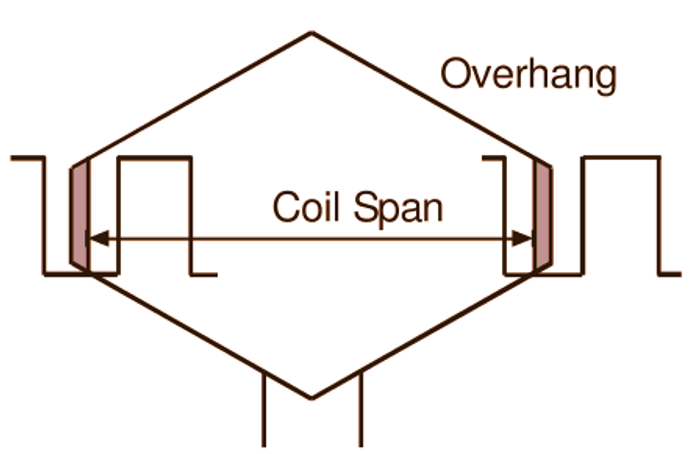
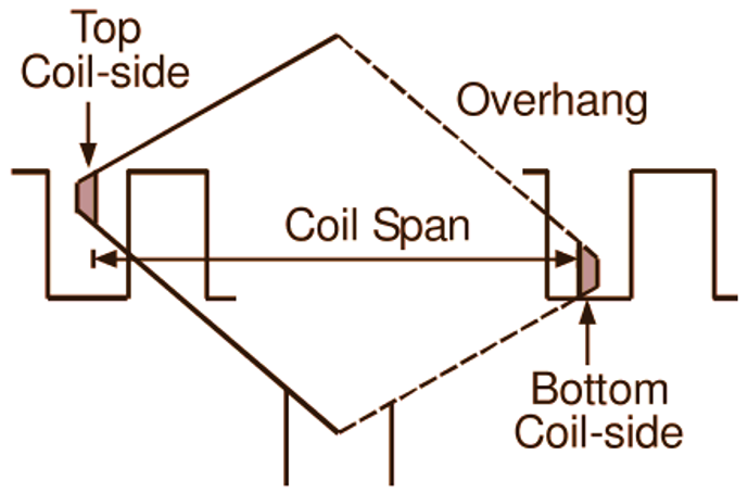
Fig. 6: Single and double layer windings
Commutator Pitch (Yc): The displacement between the commutator segments to which the two ends (i.e. start and finish) of a coil are connected is called the commutator pitch. This pitch is expressed in terms of the number of commutator segments.
Single Layer Winding: In this type of winding, the two sides of each coil are placed in the two slots separated by a distance of approximately one pole-pitch as shown in Fig. 6 (a). In this type of winding arrangement. since each side of a coil fully occupies the slot in which it is placed. there is only one coil side per slot. Single layer windings are rarely used for the armatures of dc machines.
Double Layer Winding: In this type of winding arrangement. one side of every coil lies in the top half of one slot and its other side lies in the bottom half of some other slot. normally at a distance of about one pole pitch (Fig. 6 b). Thus, there are at least two coil sides per slot.
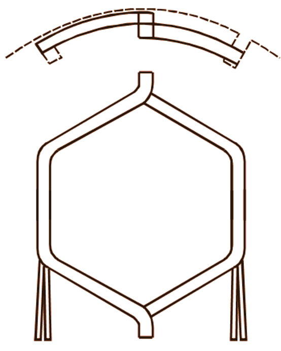
Fig. 7: Typical diamond shaped armature coil
DC armature windings are universally of the double layer type as it provides satisfactory arrangement of the end connections. For this, the coils used are diamond shaped (Fig. 7) made in special forming machines. The front and hack bends given Lo the coil are such that one coil side is on a circumferentially higher level than the other. Thus the higher side of a coil can be easily placed in the top of one slot and the lower side in the bottom of another slot.
Choice of Armature Winding
With a given number of poles (except for two poles) and armature conductors, the wave winding gives a higher e.rn.f, than the lap winding. This is because with fewer parallel paths. wave winding has a greater number of series connected conductors per parallel path. On the other hand, the number of parallel paths in a lap winding being more, for a given output current, the current per parallel path and hence the current per conductor is smaller than a corresponding value for the wave winding. Hence a smaller cross-sectional area is required for the conductor. in other words, for a given cross-sectional area of the armature conductor, current carrying capacity of the lap winding is comparatively greater. In general, the wave windings are used for high-voltage, low-current machines whereas lap windings are used for low-voltage, heavy-current machines.