In this topic, you study Differential Relay (or Differential Protection Relay) – Definition, Theory, Diagram & Types.
Differential relays are more sensitive. It is used to measure vector difference (phase/ magnitude) between two or more similar electrical quantities. Depending upon the operative principle the differential relays are categorized as follows :
- Current differential relay.
- Biased or percentage differential relay.
- Voltage balanced differential relay.
Current Differential Relay
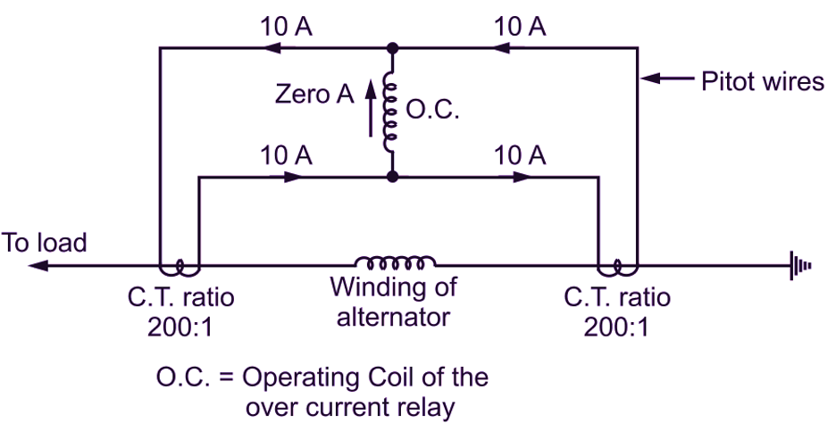
Fig. 1
The circuit shown in Fig. 1, is for alternator protection under fault condition using current differential relay. Two identical CTs are used on both sides of the element to be protected. The CTs are interconnected electrically with the help of pilot wires of high resistance (impedance). The CT ratio of both is assumed to be 200 : 1. The operating coil of over current relay is connected between two CTs pilot wires to carry the difference of currents in CT secondaries . If a current of say 2000 Amp is carried by the alternator winding and if there is no fault and operation of alternator is healthy then each CT secondary currents will be 2000/200 = 10 Amp. These induced secondary currents in both CTS are in the same direction so that net current 10 – 10 = 0 Amp. current flows through the operating coil which produce no operating signal and differential relay is inoperative. Take the case of ground fault as shown in Fig. 2.
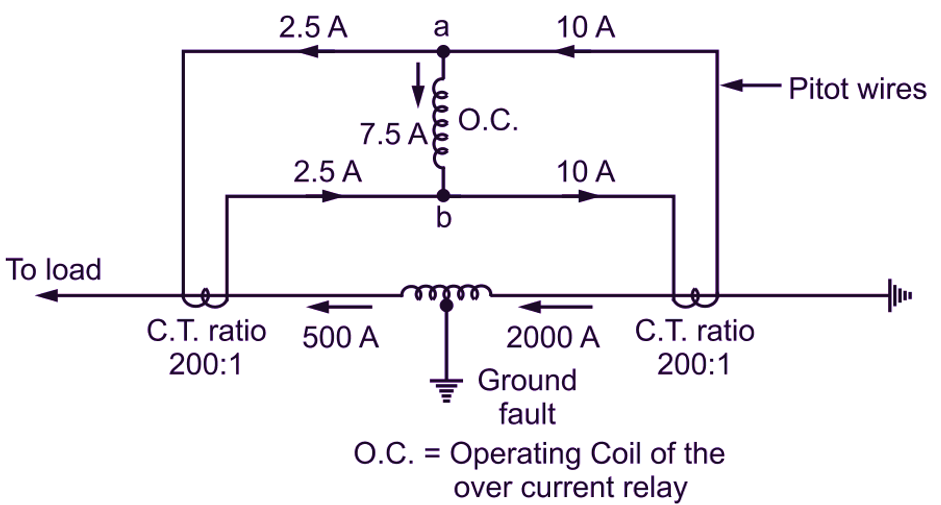
Fig. 2
Taking the case that 500 A flows on one side while 2000 A enters the other side. The currents in CTs will be 500/200 = 2.5 Amp. and 2000/200 = 10 Amp as shown in Fig. 2. The operating coil of the differential relay carries a current of 10 – 2.5 = 7.5 amps from its ends a to b. The relay operates and opens the circuit breaker and the machine is protected. In the following case, if the current flows to the fault from both the sides then sum of CTs current 10 + 5 = 15 Amp. flows through relay coil to operate the protective scheme. This circuit and current distribution is as shown in Fig. 3.
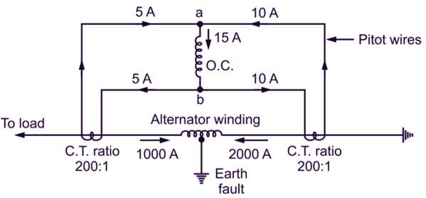
Fig. 3
Disadvantages of Current Differential Relay Protection
Though the system of differential current protection protects the machine, there are some drawbacks of this scheme of protection.
- Accurate matching of CTs cannot be achieved due to impedance of pilot circuit.
- When large through current flows, plot cable capacitance may cause maloperation.
- There is a slight difference in the two currents at two ends, this is due to pilot impedance. For the sensitive relay this small difference may cause to operate relay coil even though there is no fault.