In this topic, you study Static relay – Definition, Block Diagram, Advantages & Disadvantages.
Static relay is the relay in which there is no moving part. The comparison or measurement of electrical quantities is done by stationary network and gives the tripping signal when threshold condition is reached. Fig. 1 shows essential components of a static relay. The rectified output of the rectifier is fed to the comparator (relay measuring circuit) so output is produced when threshold condition is reached which is amplified by an amplifier. The amplified output is given to the output device which energises the trip coil.
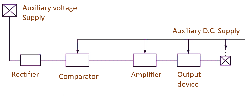
Fig.1: Static relay Block Diagram
Advantages of Static Relays
- Low power consumption: This relay provides less burden on CTS and PTS compared to conventional relays. So power consumption in measuring circuit of static relay is lower.
- No moving contacts: As there are no moving contact, there is no problem of contact bounce, arcing, erosion, replacement of contacts etc.
- There is no effect of gravity on the operation of static relays, so can be used in aircrafts.
- Resetting time and overshoot: By using special circuits, the resetting time and overshoot time can be reduced and selectivity is improved.
- Less operating time: 1 cycle, 1/2 cycle, 1/4 cycle
- Single relay for several functions: By combining various functional circuits, a single static relay can be used instead of using several relays.
- Compactness: Static relays are compact. Single relay can perform several functions.
- Better selectivity, stability and adequateness can be achieved: The relays are reliable and have excellent discriminating property if logic circuits are applied.
- Transducers: Non-electrical quantities can be converted to electrical quantities by means of transducers and then fed to static relays, hence reliability is increased and cost is also reduced.
- Remote backup and monitoring: Static relays assisted with PLCC can be used for remote backup and network monitoring.
- Repeated operations possible: Static relays can be designed for repeated operations because there is no problem of moving parts.
- Testing and servicing can be done easily: Defective part can be replaced quickly.
- Self supervision of relay
- Programmable operation
- High torque to weight ratio
Disadvantages of Static Relays
- Electrostatic discharge: Semiconductor components are sensitive to electrostatic discharge. Electrostatic charge is developed by rubbing of two insulating materials. Even small discharge can damage components which withstand 100 volt. So precautions have to be taken during manufacturing.
- Voltage transients: The static relays are sensitive to voltage spikes or voltage transient. Such transient occurs due to operation of breaker in primary circuit of CTs and PTs. Serious over voltages are produced due to breaking of control circuit, relay contacts, etc. Such voltage spikes of small duration can damage semiconductor components.
- Temperature dependence: The characteristics of semiconductors is influenced by ambient temperature. e.g. the forward voltage drop of a diode, current amplification factor of transistor changes with temperature. Temperature compensation is provided by means of thermistor circuits, digital measuring techniques etc. Individual component in circuit of relay is used in such a way that change in characteristic of component due to temperature change will not affect characteristic of the whole relay.
- Price: Higher than electromechanical relays.
- Auxiliary voltage requirement
- The characteristic is likely to be affected by the operation of output device.
- To introduce these relays in power system, enough experience should be available. Trained and skilled maintenance personal are required.
Applications of Static Relays
- Static relays are extensively used in ultra-high speed protection schemes of EHV-A.C., lines utilizing distance protection.
- It is also used in overcurrent and earth fault protection schemes.
Microprocessor Based Static Relay
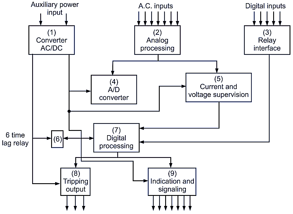
Fig. 2: Microprocessor based static relay.
Working and Components
The main components are represented in the circuit diagram shown in Figure 2.
- A.C./D.C. converter: Separation between auxiliary station battery and static relay.
- Analog processing circuit: 3-phase A.C. inputs include secondary current of C.T. and secondary voltage of P.T.
- Relay interface with external digital signals: To receive external digital inputs and to feed to block No. 7 of digital processing.
- A/D. converter: Conversion of analog digital signals into digital square wave signals.
- Current and voltage supervision: For controlling digital processes in block No. 7.
- Time lag relay: Through block No. 7 to determine operating time of backup relays.
- Digital processing: As per the required logic to process the digital signals received from A/D converter (block 4) and digital input interface (block No. 3).
- Tripping output: To give trip command to circuit breakers.
- Indication and signaling:
(a) To indicate operation of relay. (b) To provide signals to remote terminals.