In this topic, you study Potential Transformer (PT) – Working, Construction & Diagram.
These are used for measuring alternating voltages which exceed the safe value of voltmeter. They are also called as “Voltage transformers” (V. T). High voltage to be measured is first stepped down by using a potential transformer to the safe value of the Transmission line voltmeter. This process of stepping down the voltages for the purpose of measurement is called” Extension of instrument range”. This method of extension of range of instruments is superior to shunts and multipliers. The Fig. 1. shows a PT. The primary winding of P. T. is connected across the voltage V to be measured. This voltage is stepped down by the P.T. (i.e., P. T. is a step down transformer). An ordinary voltmeter is connected across the secondary of the P. T. Thus the P. T. steps down the voltage to the full scale deflection (f.s.d.) value of the voltmeter,
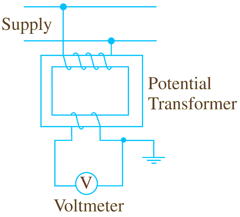
Fig. 1: Potential Transformer.
Construction of Potential Transformer (P.T.)
The P. T. in general are shell type power transformers, except that the load on P.T. is very small (in few volt-amperes). The P.Ts are used to measure high voltages, they are also used to operate relays in power system. For safety, their secondary is completely insulated from high voltage primary and also grounded for providing protection to operator. The normal secondary voltage rating is 110 V.
The P.T.s. are basically step down transformer. The primary has large numbers of turns and secondary has small no. of turns. A shell type construction is suited to P.T. as they give more accuracy. The P.T.s upto 6.6 KV are “dry” type and their higher ratings are usually oil immersed type.
The Fig. 2 shows two winding single phase potential transformer.

Fig. 1: Single-phase P.T.
Applications of Potential Transformer (P.T.)
- Potential transformers are used with voltmeters for measuring voltage or can be used with current transformers for measuring energy.
- It also used to operate protective relays and other devices.
- It is commonly used for electrical switch boards.
- It is used to extend the range of voltmeters.
- It also extends the pressure coils of wattmeters and energy meters.
Important Ponits of Potential Transformer (P.T.)
- The P.T.s. are like shell type power transformers. The important points in their construction is that they should be designed to give a constant transformation ratio and a smaller phase angle. The primary and secondary windings are coaxial to reduce the leakage reactance. The oil filled bushings are used (or oil filled C.T.s. are made) to reduce the size.
- As compared to power transformers, a potential transformer has larger core.
- The output of P. T. is always small and its size is quite large; so there is no problem due to rise in temperature.
- Usually, cotton tape and varnished cambric are used as insulation. Hard fibre “separators” are also used in between the coils.
- There is no danger, if the secondary winding of a P. T. is left open circuited.