The alternator has the following parts:
- Stator.
- Rotor.
- Exciter.
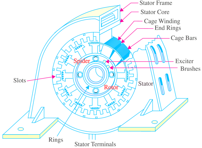
Stator
It is a stationary portion consisting of stator frame and stampings etc. The stator frame is used for holding the armature stampings and the stator winding in position. Depending upon the capacity some holes are provided or casted in the frame to circulate the air for cooling. In big frames, the horizontal and vertical ducts are made for the air to circulate or heat dissipation i.e. for cooling purpose. The stampings are made of laminations of silicon steel. Each lamination is insulated from each other by means of paper or varnish layer or oxide coating or enamel coating. There are number of slots provided in the laminations to house the winding. The slots are of these types, open type, having same opening from top to and bottom, semi-closed, having small opening and closed type which are totally closed as shown in Fig. 1. The slots. which are cut in the inner periphery of the laminations are generally open types or semiopen types of slots. The winding is placed in the slots and the conductors are held in position by means of the fiber or bamboo wedges.
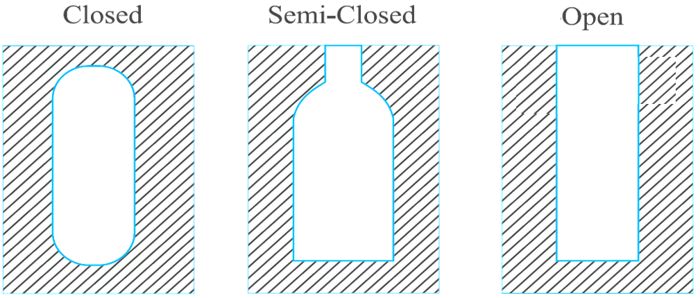
Fig. 1: Types of slots
Rotor
It is a rotating portion of the alternator. The rotors are of two types:
- Salient pole type.
- Smooth cylindrical type.
Salient pole rotor
In this type of rotor, the poles are projected having large diameter and less axial length. These are suitable for low and medium speed. As the speed is less so the number of poles can be more i.e. from 6 to 40. The poles cores assembly is bolted or dovetail joined to the cast iron or steel wheel as shown in Fig. 2.
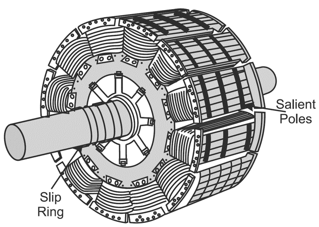
Fig. 2: Salient pole rotor
Smooth cylindrical rotor
These rotors are having less diameter and more axial length. The rotors are consisting of a smooth solid forged steel cylinder. As the diameter is less, these are suitable for high speed. Generally these are used for steam or turbo alternators which runs at a very high speed. The number of poles are either two or four resulting speed as 3000 rpm or 1500 rpm. The slots are made on the outer periphery as shown in Fig. 3. This can be said a non-salient type pole. These are much balanced and smooth in operation. The fans are also constructed to enable the air circulation for cooling.
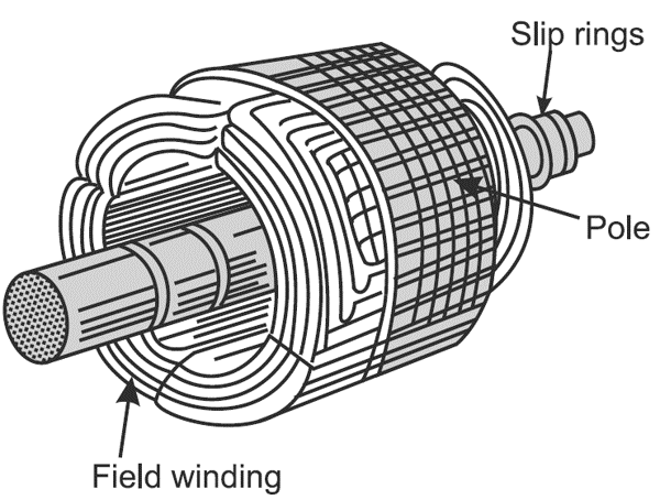
Fig. 3: Smooth cylindrical rotor.
Exciter
To excite the field windings of the alternator the exciter in used. It can be a d.c. shunt generator or some times a d.c. compound generator. Normally the exciter is mounted on the same shaft. The exciting current is supplied to the alternator through two slip rings and brushes etc. The exciting voltage varies from 125 V to 250 V with the power rating 0.3 to 1
Which type of the field construction is preferred? What are the advantages of using rotating field type construction?
The field of an alternator can be of two types:
(i) Stationary field.
(ii) Rotating field.
Generally the rotating field type construction is used.
Advantages: There are the following advantages of using a rotating field type construction:
- Only two slip rings are essential for the alternator whatsoever the number of phases may be.
- As the winding is placed over the stator, more conductors can be housed in the stator because of more internal peripheral area.
- As the winding in which e.m.f. is induced, is stationary (Figure 4), so there is no possibility of breaking or loosening the winding and its joints.
- There is no sliding contact between the armature and external (load) circuit, only two slip rings are provided for field excitation, thus less sparking and less possibility of faults.
- The winding being stationary can be easily and effectively insulated and the insulation cost will also be less (less dielectric strength insulation can work).
- Armature can have more number of conductors so e.m.f. induced will be more.
- Less maintenance and possibility of faults.
- As the rotor is light so can be driven at higher speed.
- The current of rotor winding is independent of the capacity of the alternator, hence lighter rotor can be used than the rotating armature type alternators.
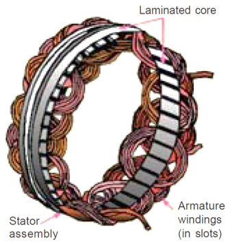
Fig. 4: Stationary armature windings