In this topic, you study Alternator or Synchronous Generator Construction.
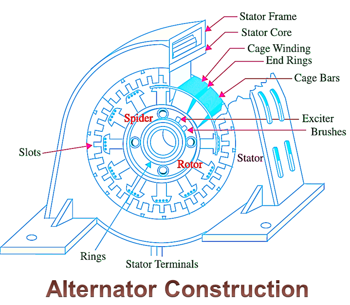
Almost all alternators are constructed with a stationary armature and rotating poles, except some of the smaller low voltage alternators in which the armature rotates within the stationary field structure. Therefore, let us see the general constructional features of only such alternators in brief. The revolving field type practical three-phase alternator has the following main parts:
Stator
The stationary armature is normally called stator (stationary member). It consists of the iron core and the armature winding. (Fig. 1).
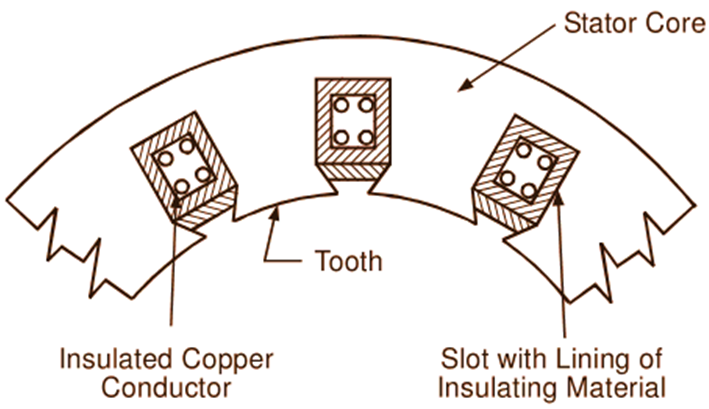
Fig. 1: Portion of an alternator stator
The magnetic core of the Stator is built-up of special steel stampings insulated from each other with paper, varnish or oxide coating. These laminations are in the form of complete rings for smaller machines and in segments for larger machines. The laminated construction of the cote minimizes the iron loss occurring in it (as the stator core is continuously cut by the rotor field). The built-up core is housed in a frame which is usually fabricated from steel plates. The frame carries no flux and serves merely as a mechanical support. Both radial and axial air ducts are provided in the core for ventilation purposes. For axial ducts, the series of holes are provided through the stampings. On the other hand, radial air ducts are provided by placing spacers between the stacks of the laminations. The slots (open, semi-closed or fully closed type) cut around the inner surface of the core hold the conductors of the armature winding. These conductors are well insulated from each other and from the core.
Rotor
The rotating field system of the alternator is normally known as rotor (rotating member). There are two types of rotor:
Salient Pole Rotor
In this type of rotor, all the poles project out from the surface of the rotor. Hence, it is termed as projected or salient pole type rotor. This type of rotor is suitable only for low speed machines, particularly those driven by hydraulic turbines. The alternators with salient pole type rotors have large diameters (to accommodate the large number of poles on the rotor) and short axial lengths. The poles built up of thick steel stampings riveted together are either bolted or dovetailed to the rotor spider as shown in Fig. 2. The pole face is suitably shaped so as to obtain increasing radial air-gap length from the pole centre to pole tips. This makes the flux distribution over the armature approximately a sine wave and thereby helps to generate sinusoidal waveform of e.m.f. The overhang of the pole-shoes provides mechanical support for the field coils which are often wound using rectangular copper strip. The pole-shoes are slotted for housing copper bars of a damper winding (also called an amortisseur winding). These bars are short-circuited at both ends by heavy copper rings similar to squirrel-cage winding of an induction motor. The damper winding is necessary for preventing momentary speed fluctuations (which may be caused by sudden or periodic variation in the load, in the impressed voltage or in the excitation) called hunting. So long as the rotor rotates at synchronous speed, there is no relative motion between the rotating field of the armature and the conductors of the damper winding, and the damper winding has no effect on the operation of the machine. But as soon as the speed of the rotor departs from the synchronous speed, there is relative motion between the rotating field and the damper winding and currents are induced in the damper winding conductors. In accordance with Lenz’s law, these currents are in such a direction that they tend to pull the rotor back into synchronism and thus the hunting is prevented. As projected poles produce fan action, cooling is more effective in the alternators with salient pole type rotors.
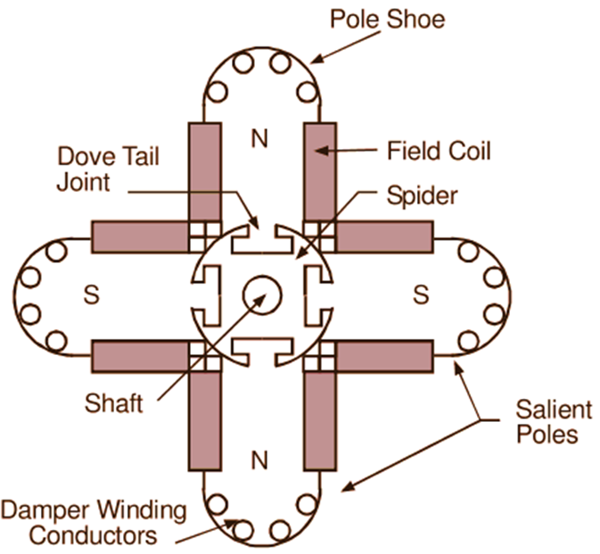
Fig. 2: Salient Pole
Non-Salient or Cylindrical Rotor
The rotors of the high speed alternators driven by steam turbines (turbo-alternators) are of this type. The cylindrical rotor is a solid steel forging with a small diameter to keep the peripheral speed within limits and consequently has large axial length. The field winding is firmly embedded in the slots cut on the outer surface of the rotor. These slots are covered at the top with steel, manganese or phosphor bronze wedges to hold the conductors in position. The winding is arranged to form two or four distinct field poles. The unslotted portion of the rotor forms pole faces as shown in Fig. 3. The main advantage of cylindrical construction is mechanical robustness. Only with this type of construction can the rotor withstand the terrific centrifugal force developed at high speeds without flying apart. Solid field poles themselves act as efficient dampers. Hence separate damper winding is not generally necessary. With cylindrical construction, due to distribution of field winding in several slots, the flux distribution around the periphery of the armature (i.e. in the air gap) is nearly a sine wave. Consequently, a better e.m.f. waveform is obtained. Better balance, quiet operation and less windage loss are some other advantages of the cylindrical construction of the rotor. Ventilating holes are provided below each slot for cooling purposes. For proper cooling, forced air cooling or hydrogen cooling is invariably employed for large machines using this type of construction.
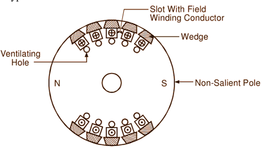
Fig. 3: Smooth cylindrical rotor
Exciter
Regardless of the type of rotor used, its winding is separately excited, usually by a small dc generator called an exciter. The exciter generally mounted on the same shaft supplies direct current for the field magnets at low voltage of the order of 110 to 250 V through the slip-rings. Modern trend, however, is to use static exciters for providing the necessary excitation for the field winding.