In spite of the presence of torque ripples and higher acoustic noise, Switched Reluctance Motors are used in numerous applications because of their high starting torque, high torque to inertia ratio, high reliability, wide speed range, fast response, ruggedness, and low cost.
Constructional of Switched Reluctance Motor
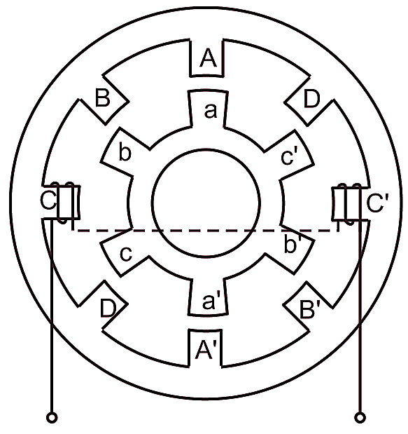
Fig. 1 shows the cross-section of a typical 4-phase switched reluctance motor having eight poles in the stator and six poles on the rotor. Both the stator and rotor have laminated construction to reduce the core losses and have salient poles. While the rotor has no windings or permanent magnets, each stator pole has a concentrated winding around it. Each pair of diametrically opposite coils are connected in series and form one phase of the motor. In the figure, only one phase winding is shown for simplicity.

Fig. 1: Schematic diagram of a 4-phase switched reluctance motor.
Switched Reluctance Motor drive Block diagram
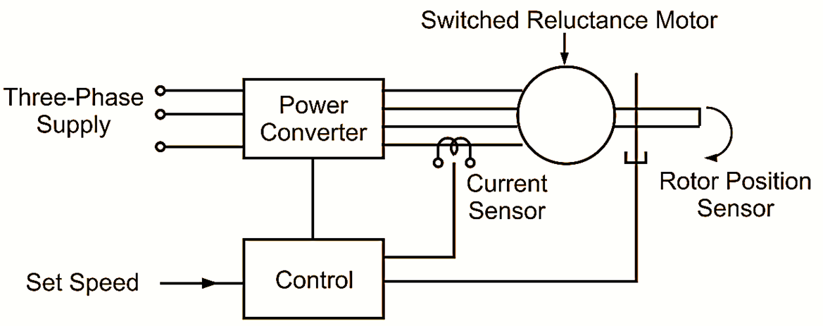
The complete drive system comprises of a switched reluctance motor coupled with a load, a power converter, a control system involving rotor position transducer and current sensor as shown in Fig. 2.

Fig. 2: Block diagram of a switched reluctance motor.
Principle of Operation Switched Reluctance Motor
Torque is produced by exciting any phase of the stator winding by means of unidirectional current. This results in the magnetic attraction of an adjacent rotor pole as it tends to align into a position of minimum reluctance. When the number of stator and rotor poles differ, the sequential switching of the excitation from one set of stator poles to the next, in synchronism with the rotor position, results in an almost constant torque causing uniform rotation. The synchronization of the switching on of the excitation with rotor position can be accomplished with simple rotor position feedback.
Torque-Speed Characteristic of Switched Reluctance Motor
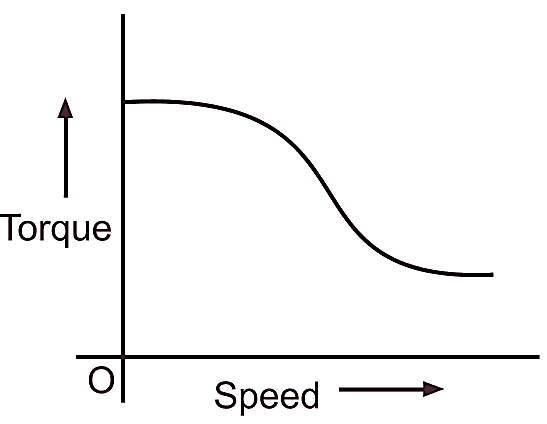
Fig. 3 shows the torque-speed characteristic of a switched reluctance motor with the simplest form of a control. From the figure, it will be observed that the starting torque of such a motor is high. By choosing appropriate switching angles and current levels together with an appropriate electromagnetic design, torque-speed characteristics of the switched reluctance motor can be tailored to suit the application.

Fig. 3: Torque-speed characteristic of a switched reluctance motor with the simplest form of control.
Reversal of Rotation of Switched Reluctance Motor
The direction of rotation of a switched reluctance motor can be reversed by reversing the sequence of switching the current into the stator windings.
Applications of Switched Reluctance Motor
The applications of these motors include compressors, fans, centrifuges, food processors, washing machines, vacuum cleaners, fluid pumps, process control industries, hybrid/electric vehicles, electromechanical brake systems, electric power steering, starter generator systems, aircraft applications, servo drives, etc.