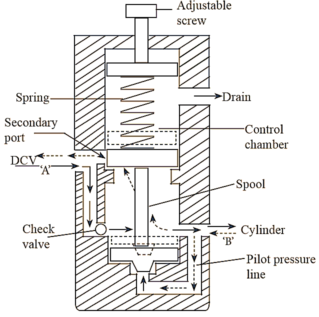
Counterbalance valves are used to maintain the back pressure on a vertical cylinder to prevent the load from falling due to gravity.
Construction of Counterbalance Valve
It consists of a spring operating control chamber to which a drain line is provided to return the leaked fluid. It lias two ports, one is connected to the rod end of cylinder and another is to directional control valve (DCV). A check valve is provided to allow the flow only in one direction and in another direction is blocked. In this type, valve is set to a pressure greater than load pressure of the cylinder. A pilot pressure line is provided inside the valve which connects the orifice below the spool and cylinder port ‘B’. The schematic counterbalance valve is shown in figure 1.

Figure 1: Counter-balance Valve.
Working of Counterbalance Valve
It is a normally closed type valve. Initially, the fluid from directional control valve (DCV), enters into the through the counterbalance valve through the port ‘A’ and leaves through the port ‘B’. Thus, the fluid enters the rod end of the vertical cylinder. Due to fluid pressure, piston moves upward. When the oil under pressure is supplied to the cylinder blind end directly by the DCV, the force due to load attached to piston or gravity and the oil pressure acts downwards. Due to this, the fluid at rod end of cylinder gets pressurised. Then, the pressurised fluid returns to the counterbalance valve through port ‘B’ and transmitted to the spool through the pilot pressure line. By which, the spool moves up against the spring force and fluid will flow to the directional control valve through the secondary port. While spool is moving up, some amount of fluid leaked into the control chamber past the spool and this leaked fluid is return to the tank through the drain line.