In this topic, you study the theory and diagram of Air Friction Damping or Pneumatic Damping.
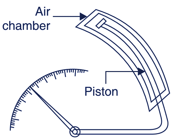
In this chamber method, a light aluminium piston (or vane) is attached to spindle. The piston moves in a rectangular (or circular) air chamber closed at one end. There is very little clearance in chamber for the movement of the piston. See Fig 1 (a).
- When the pointer moves clockwise the piston comes out of the air chamber so that the pressure inside the chamber becomes less as compared to the atmospheric pressure outside the chamber and as a result the piston (and the moving system of the instrument) are opposed in their rapid motion, i.e., their movement is checked.
- When the pointer moves anticlock wise, the piston is pushed in to the chamber; the air inside the chamber is pressed so that the pressure inside the chamber becomes higher than the atmospheric pressure outside and as result, the Piston (hence the moving system) are opposed in rapid motion i.e., their speed of motion is again checked.

(a)

(b)

(c)
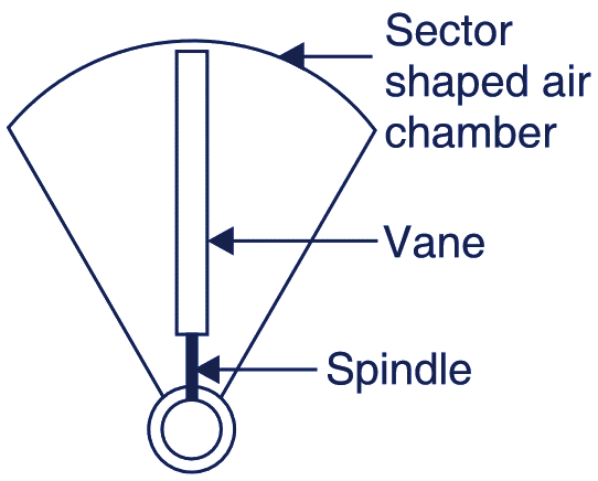
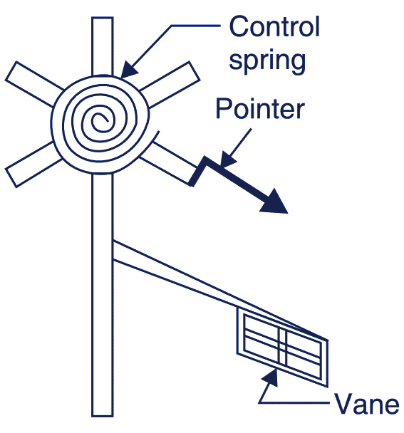
Fig. 1. Air Friction Damping
In this way, the motion of the moving system clockwise (as well as anticlockwise) is checked and the pointer’s oscillation are damped. The Fig. 1 (b) shows another arrangement of air friction damping. It consists of an aluminium vane which moves in a sector shaped air chamber. There should be very little clearance between vane and the walls or the chamber.
The Fig. 1 (c) shows yet another arrangement of air friction damping, in which a vane is attached with the spindle itself. Air Friction damping provides a very simple and cheap method of damping. But care must be taken that the piston is not bent or twisted, otherwise it will touch walls of the chamber, thereby causing serious errors. This method is used in moving iron and hot wire instruments.