Whenever the alternator is supplying the load, the load current will flow through the conductors, producing the magnetic field, proportional to the load current. The armature reaction is defined as “the effect of the magnetic field produced by the armature conductors on the distribution of magnetic flux under the main poles”. The load on the alternator is not only of one nature but it is of resistive, inductive or capacitive nature.
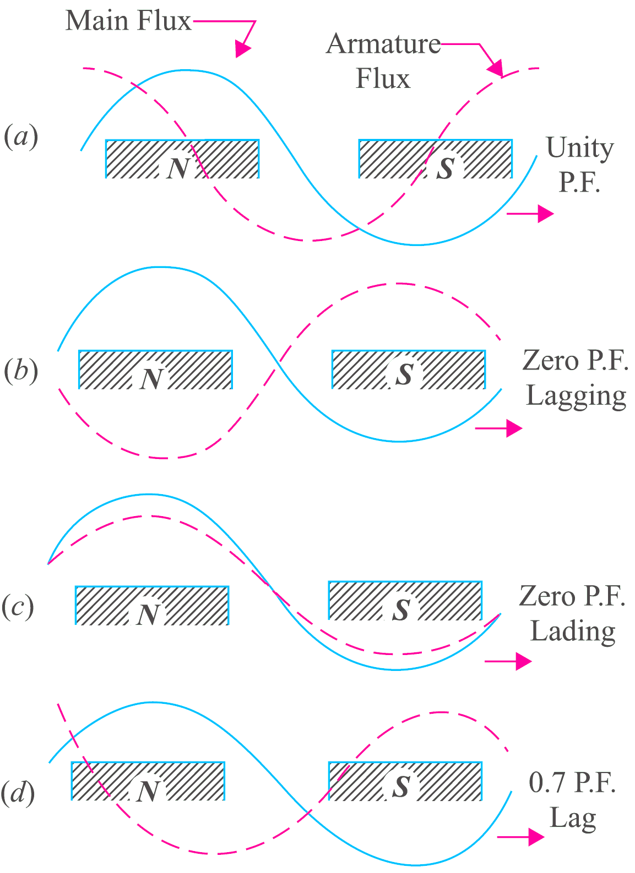
Fig. 1: Armature Reaction in Alternator
Purely resistive load (Unity P.F.)
Whenever the load is of purely resistive nature i.e. having unity power factor, the armature coil will carry maximum Current, in which maximum e.m.f. is induced. Then the magnetic field produced by the conductor will drift the main magnetic field as shown in Fig. 1 (a). The net effect will be the lagging of armature flux wave behind the main flux by π/2. Thus the flux will be weak at leading pole tips and strong at trailing pole tips and the main flux is distorted.
Purely inductive load (Zero P.F. lagging)
Whenever the inductive load is connected, it means the current lags behind the voltage by 90°. The armature coil will carry the maximum current which is 90°, behind the coil inducing maximum e.m.f. Otherwise also we can say that if the coil at magnetic axis inducing maximum e.m.f., the coil at MNP will carry maximum current, and the net result will be the demagnetising as shown in Fig. 1 (b).
Purely capacitive load (Zero P.F. leading)
In this case the current will lead the voltage by 90°, so the coil ahead by 90° will have maximum current then the coil producing maximum voltage. Thus the current will establish the flux which will strengthened the main flux as shown in Fig. 1 (a).
But in practice the load is not of pure nature but a mixed one as shown in Fig. 1 (d). Let us have a load having power factor as cos Φ. This power factor will cause the armature to have cross magnetising and demagnetising fluxes. The cross magnetising component will be proportional to I cos Φ and the demagnetising component proportional to I sin Φ.