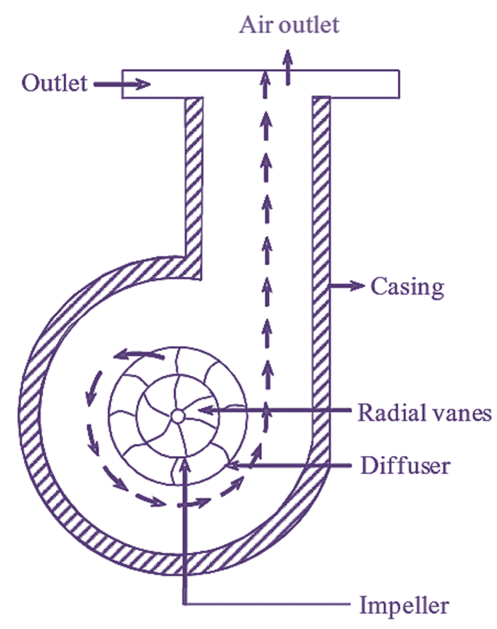
Figure 1: Centrifugal Air Compressor.
A Centrifugal Air Compressor consists of a rotor (or impeller) to which a number of curved vanes are fined symmetrically. The rotor rotates in an air tight casing with inlet and outlet points.
The casing is so designed that the kinetic energy of the air is convened into pressure energy before it leaves the casing. The mechanical energy to the rotor is provided by some external source. As the rotor rotates, it sucks the air through its inlet, increasing its pressure due to centrifugal force and forces the air to flow over the diffuser. In the diffuser, the pressure of air is father increased and hence the air is passed onto the receiver.
Parts of Centrifugal Air Compressor
The essential components that are required for the operation of centrifugal compressor are,
- Inlet pipe
- Curved radial vanes
- Impeller
- Casing
- Diffuser
- Outlet pipe.
1. Inlet Pipe: The main purpose of inlet pipe is to introduce the fluid into impeller inlet.
2. Curved Radial Vanes: A series of curved vanes mounted on the shaft and they rotate with the shaft. The movement of air is guided by the radial vanes. The fluid flows radially outwards through impeller because of these radial vanes.
3. Impeller: The rotating member in centrifugal compressor is impeller. The fluid is rotated by the impeller and increases both pressure and velocity of the fluid.
4. Diffuser: It contains diverging passages formed by the diffuser blades. By passing through these passages, the velocity of air decreases and pressure increases still further.
5. Casing: The casing surrounds the totaling impeller. It collects the high pressure air from diffuser.
6. Outlet Pipe: Compressed air is taken out through outlet pipe.
Expression for Workdone in a Centrifugal Air Compressor


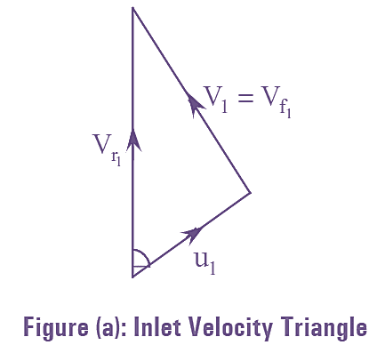
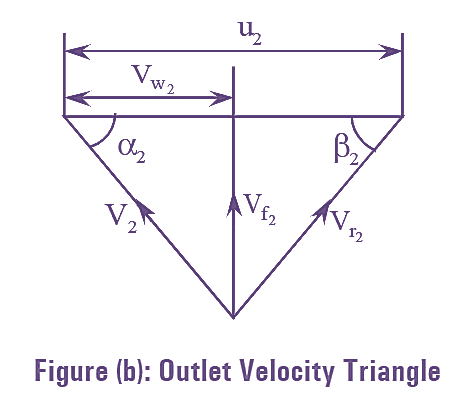
The work done by the impeller of a centrifugal compressor can be derived by considering the inlet and outlet velocity triangles as shown in the figures (a) and (b). Assuming that the air enters axially, hence the velocity of whirl at inlet is zero, therefore, V1 = Vf1
Let mass of the fluid enters the impeller is one kg.
According to the principle of moment of momentum, theoretical torque supplied to the impeller must be equal to the rate of change of momentum.
Therefore,
\[\text{Workdone}=\text{Torque}\times \text{Angular Velocity}\]
\[\text{W}\text{.D}=T\times \omega \]
\[=({{V}_{{{w}_{2}}}}{{r}_{2}}-{{V}_{w1}}{{r}_{1}})\omega \]
\[={{V}_{{{w}_{2}}}}{{r}_{2}}\omega -{{V}_{w1}}{{r}_{1}}\omega \]
Also
\[{{r}_{1}}{{\omega }_{1}}={{u}_{1}}\text{ and }{{r}_{2}}{{\omega }_{2}}={{u}_{2}}\]
But,
\[\left( {{V}_{w2}}{{u}_{2}}-{{V}_{w1}}{{u}_{1}} \right)=\left( {{h}_{2}}-{{h}_{1}} \right)\]
\[{{h}_{2}}-{{h}_{1}}={{C}_{p}}({{T}_{2}}-{{T}_{1}})\]
Therefore,
\[\text{W}\text{.D}=\left( {{V}_{w2}}{{u}_{2}}-{{V}_{w1}}{{u}_{1}} \right)\]
\[={{h}_{2}}={{h}_{1}}={{C}_{p}}({{T}_{2}}-{{T}_{1}})\]
The above equation is known as Euler’s work.
If the fluid enters the impeller radially then Vw2 = 0. Work done = Vw2 u2 J/kg.
From inlet and outlet velocity triangles, we have,
\[V_{r1}^{2}=u_{1}^{2}+V_{1}^{2}-2{{u}_{1}}{{V}_{w1}}\]
\[V_{r2}^{2}=u_{2}^{2}+V_{2}^{2}-2{{u}_{2}}{{V}_{w2}}\]
By substituting the values of Vw2u2 and Vw1u1 , from the equations (2) and (3) in equation (1).
\[\text{W}\text{.D}=\frac{V_{2}^{2}-V_{1}^{2}}{2}+\frac{V_{r1}^{2}-V_{r2}^{2}}{2}+\frac{u_{2}^{2}-u_{1}^{2}}{2}\]
In the above equation, the term $\left[ \frac{V_{2}^{2}-V_{1}^{2}}{2} \right]$ represents the increase in kinetic energy of fluid.
The term $\left[ \frac{V_{r1}^{2}-V_{r2}^{2}}{2} \right]$ represents the pressure rise in the impeller due to diffusion action. Whereas the term $\left[ \frac{u_{2}^{2}-u_{1}^{2}}{2} \right]$ represents the pressure rise in the impeller due to centrifugal action.