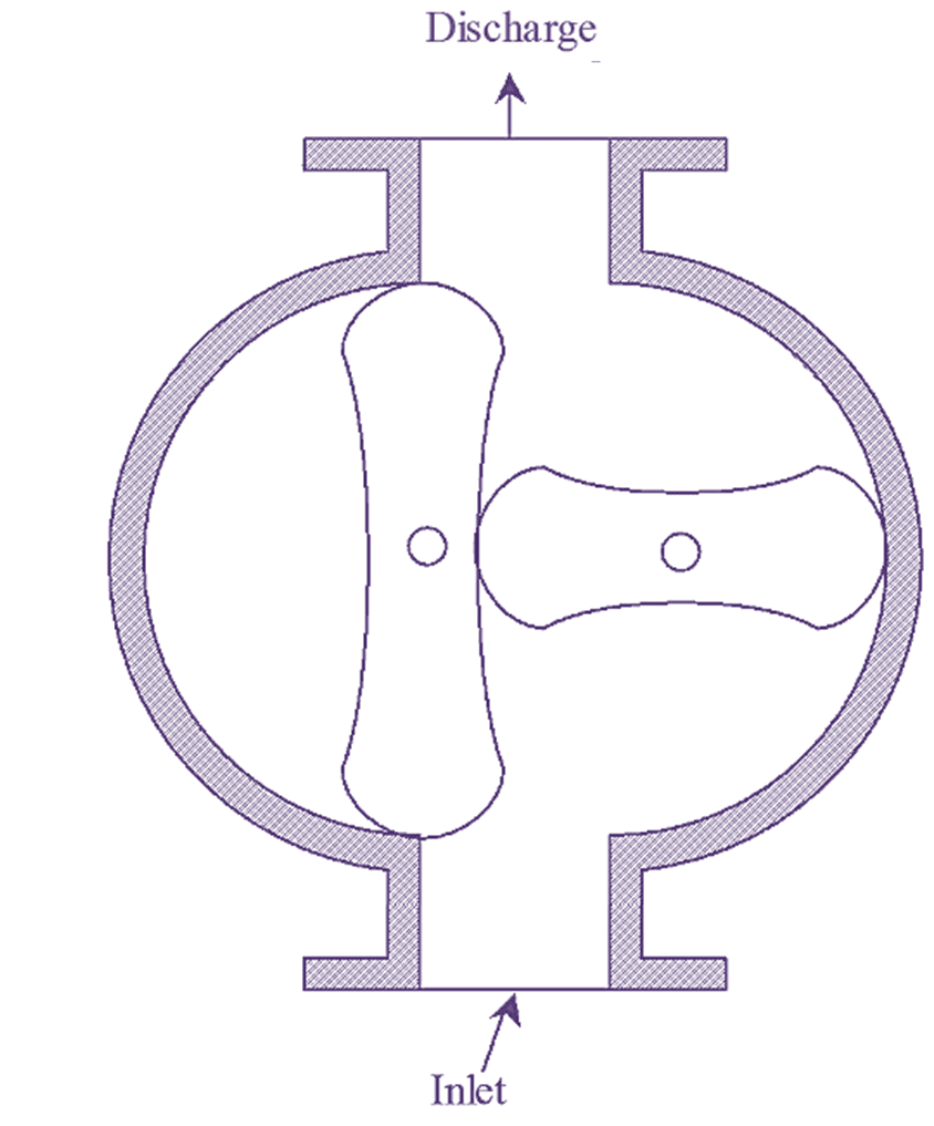
Figure 1: Roots Blower.
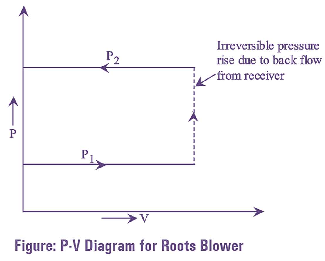
The roots blower compressor consists of two rotors or lobes arranged on two separate axes as shown in figure 1. One of the rotors is directly connected to a drive and the other is driven by gear connected to the first. These rotors rotate in opposite direction to each other. The rotor or lobes are of cycloidal or involute profile and are connected in such a way that it seals the delivery side from the suction or inlet side. A small clearance is to be provided between the lobes, casing for reducing wear and friction. The provided clearance acts as a leakage passage and hence affects the performance of the compressor. From the intake port, the air enters into the casing and the air trapped between the rotors or lobes moves along the port and then discharged through the discharge port to the receiver. But, when the outlet port is open. The gas from the receiver flows back, as it is at higher pressure. The gas is compressed irreversibility to the delivery pressure and then delivery begins. This process is carried out four times in one revolution of the driving shaft. It is shown in P-V diagram by dotted lines.
Efficiency of Roots Blower
Let. P1– Pressure of air at inlet
T1– Temperature of air at inlet
V – volume between lobe face and the casing
VS – Swept volume
P2 – Pressure of air after compression.
Workdone per cycle = (P2 – P1)V
Workdone per revolution = 4(P2 – P1)V
Workdone/minute = (P2 – P1)VS
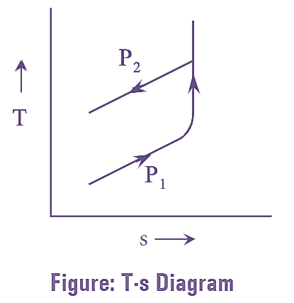
For an ideal compression process i.e. reversible adiabatic process the work done per minute is given by,
\[\text{Workdone/Minute}=\frac{\gamma }{\gamma -1}{{P}_{1}}{{V}_{S}}\left[ {{\left( \frac{{{P}_{2}}}{{{P}_{1}}} \right)}^{\frac{\gamma -1 }{\gamma}}}-1 \right]\]
Roots blower efficiency is given as the ratio of isentropic workdone to the actual work done.
i.e.,
\[\text{roots blower efficiency}=\frac{\text{Isentropic workdone}}{\text{Actual workdone}}\]
\[{{\eta }_{roots}}=\frac{\frac{\gamma }{\gamma -1}{{P}_{1}}{{V}_{S}}\left[ {{\left( \frac{{{P}_{2}}}{{{P}_{1}}} \right)}^{\frac{\gamma -1 }{\gamma}}}-1 \right]}{{{V}_{S}}({{P}_{2}}-{{P}_{1}})}\]
\[{{\eta }_{roots}}=\frac{\frac{\gamma }{\gamma -1}{{P}_{1}}{{V}_{S}}\left[ {{\left( \frac{{{P}_{2}}}{{{P}_{1}}} \right)}^{\frac{\gamma -1 }{\gamma}}}-1 \right]}{{{P}_{1}}{{V}_{S}}\left[ \frac{{{P}_{2}}}{{{P}_{1}}}-1 \right]}\]
\[=\frac{\frac{\gamma }{\gamma -1}\left[ {{\left( \frac{{{P}_{2}}}{{{P}_{1}}} \right)}^{\frac{\gamma -1 }{\gamma}}}-1 \right]}{\left[ \frac{{{P}_{2}}}{{{P}_{1}}}-1 \right]}\]
\[\frac{{{P}_{2}}}{{{P}_{1}}}=r=compression\text{ }ratio\]
\[{{\eta }_{roots}}=\frac{\gamma }{\gamma -1}\frac{\left[ {{\left( r \right)}^{\frac{\gamma -1 }{\gamma}}}-1 \right]}{\left( r-1 \right)}\]
Since,
\[\frac{\gamma }{\gamma -1}=\frac{{{C}_{p}}}{R}\]
\[{{\eta }_{roots}}=\frac{{{C}_{p}}}{R}\left[ \frac{{{\left( r \right)}^{\frac{\gamma -1 }{\gamma}}}-1}{r-1} \right]\text{ }\]
From the above equation, it can be noticed that the roots efficiency decreases with increase in pressure ratio and can be used up to a pressure ratio of 2 for single stage and 3 for two- stage only. These compressors are generally designed for the capacities varying from 0.14 m3/min, to 1400 m3/min.