After reading this topic First order control system, you will understand the theory, the open and close loop transfer function, Pole zero map, examples and block diagram.
In a system whose transfer function having the highest power of s equal to 1 in its denominator, is called the first order control system.
Closed-loop transfer function and block diagram
A block diagram of first order closed – loop control system with unity negative feedback is shown below in Figure 1,

Figure 1 First order control system block diagram. www.electricalworkbook.com
It is given unity negative feedback $H(s)$ so,
\[H(s) = 1\]
The open loop transfer function $G(s)H(s)$ of the first-order control system can be written as
\[G(s)H(s) = \frac{1}{{sT}}.1\]
So, the close loop transfer function of first order control system can be written as
\[\frac{{C(s)}}{{R(s)}} = \frac{{G(s)}}{{1 + G(s)H(s)}} = \frac{{1/sT}}{{1 + (1/sT)}} = \frac{1}{{1 + sT}}….(1)\]
Equation 1 describe the standard form of a first – order system.
Pole-zero map
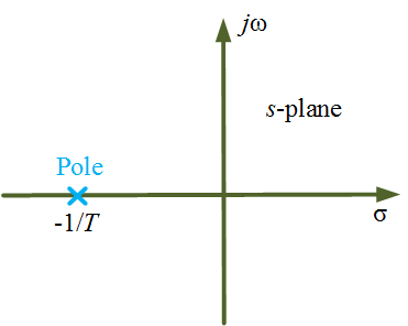
Using Equation 1, the Pole-zero map of a first-order system is shown below in Figure 2.

Figure 2 First order Control System Pole zero map. www.electricalworkbook.com
Examples
Thermometer, thermal system, overhead tank, gas cylinder, series RL network, series RC network
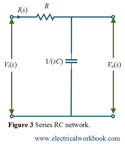
Consider the series RC network which is an example of a first – order system, as shown below in Figure 3.

Using KVL gives,
\[{V_i}(s) = I(s)\left( {R + \frac{1}{{sC}}} \right)\]
or,
\[{V_i}(s) = I(s)\left( {\frac{{1 + sCR}}{{sC}}} \right)….(2)\]
Output voltage ${V_o}(s)$ can be written as,
\[{V_o}(s) = I(s)\left( {\frac{1}{{sC}}} \right)….(3)\]
\[{\text{Using Equation 2 and Equation 3 gives,}}\]
\[\frac{{{V_o}(s)}}{{{V_i}(s)}} = \frac{1}{{1 + sCR}}….(4)\]
Comparing Equation 1 and Equation 4 gives,
\[T = RC\]
where T is the time constant of series RC network.