After reading this topic Unit impulse input time response of a first order control system, you will understand the theory, expressions, and derivation.
A block diagram of first order closed – loop control system with unity negative feedback is shown below
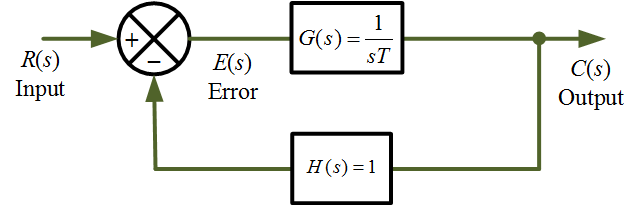
Figure 1 First order control system block diagram. www.electricalworkbook.com
The general output C(s) for the first order control system as
\[C(s) = R(s)\frac{1}{{1 + sT}}….{\text{(1)}}\]
The input R(s) to the system is unit impulse function, so in the s – domain
\[R(s) = 1\]
Hence, Equation1 gives
\[C(s) = 1.\frac{1}{{1 + sT}}{\text{ = }}\frac{1}{T}.\frac{1}{{s + (1/T)}}……{\text{(2)}}\]
Applying inverse laplace transform on both sides of Equation 2,
\[{\mathscr{L}^{{\text{ – 1}}}}C(s) = {\mathscr{L}^{{\text{ – 1}}}}\left[ {\frac{1}{T}.\frac{1}{{s + (1/T)}}} \right]\]
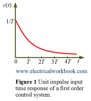
\[c(t) = \frac{1}{T}{e^{ – t/T}}….(3)\]
The time response c(t) of Equation 3 is shown below in Figure 1.