In this topic, you study Fluorescent Lamp – Working Principle, Construction & Circuit Diagram.
The fluorescent lamp is a low-pressure mercury discharge lamp.
Construction of Fluorescent Lamp
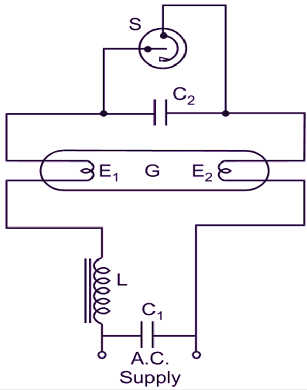
The fluorescent lamp (Fig. 1 (a) and Fig. 1 (b)) generally consists of a long glass tube (G) with an electrode at each end (E1 and E2). These electrodes are made of coiled tungsten filament coated with an electron emitting material. The tube is internally coated with a fluorescent powder and contains a small amount of argon together with a little mercury at a very-low pressure. The control circuit of the tube consists of a starting switch (S) known as a Starter, an iron-cored inductive coil called a choke (L) and two capacitors (C1 and C1).

(a)

(b)
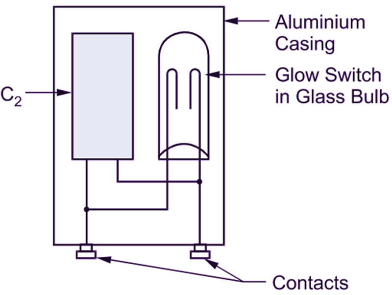
Fig. 1: (a) Fluorescent lamp circuit with a glow type starting switch, (b) Cutaway view of a starter
Working Principle of Fluorescent Lamp
Two types of starting switches, namely the glow type (a voltage operated device) and the thermal type (a current operated device) are in general use. A tube fitted with a glow type starter (S) is shown in Fig. 1 (a). This starter (Fig. 1 b) consists of two electrodes hermetically sealed in a glass bulb filled with a mixture of helium and hydrogen. One electrode is fixed and the other is a U-shaped bimetallic strip made of two metals having different temperature co-efficients Of expansion. The contacts are normally open. When the supply is switched on, heat produced due to a glow discharge between electrodes of the starter is sufficient to bend the bimetallic strip (due to uneven expansions of two metals) until it makes contact with the fixed electrode. Thus, the circuit between two tube electrodes (E1 and E2) is completed and a relatively large current is circulated through them. The electrodes are then heated to incandescence by this circulating current and the in their immediate vicinity is ionized. After a second or two, due to the absence Of a glow discharge which ceases after the closing of the contacts of the starting switch, the bimetallic strip cools sufficiently. This causes it to break contact and the sudden reduction of current induces an e.m.f. of the order of 800 – 1000 V in the choke coil. This voltage is sufficient to strike an arc between the two electrodes E1 and E2 due to the ionization of argon. The heat generated in the tube vaporizes the mercury and the potential difference across the tube falls to about 100-110 V. This potential difference is not sufficient to restart the glow in the starter. If a thermal type starting switch is used, the circuit arrangement will be as shown in Fig. 2. This switch (S), either open type or enclosed in a hydrogen filled glass bulb, has a bimetallic strip close to a heater element (R). The two electrodes of the switch are normally closed. Consequently, when the lamp is switched on, the circuit being complete through the thermal switch, a relatively large current flows through the two filaments (E1 and E2) of the tube. This circulating current heats the filaments to incandescence and the gas in their immediate vicinity is ionized. Since the same current is also passing through the heater element (R), it causes the bimetallic strip to break contact and the inductive voltage surge due to the choke starts the discharge in the tube. The starter contacts, then remain open till the lamp is in operation due to the heat generated in the heater element.

Fig. 2: Fluorescent lamp circuit with thermal type starting switch
Most of the energy radiated by this low-pressure mercury vapour lamp is not in visible form. The fluorescent coating absorbs this energy and converts it into visible radiation i.e. light. Different fluorescent powders re-radiate the absorbed energy at different colours.
Functions of the Auxiliary Circuit Components
Choke
- It provides a necessary high voltage to start the discharge in the tube (i.e. the voltage required to strike an arc between the two electrodes of the tube).
- Since the voltage required across the tube during normal operation is small (about 100-110 V), the excess voltage is dropped across the choke.
- The choke acts as a stabilizer. The discharge has a negative characteristic i.e. the resistance falls with an in current. Under such conditions, the choke helps in maintaining a constant current in the tube. For example, if the current increases, the voltage drop across the choke will increase and the voltage across the tube will decrease which will tend to decrease the current and vice-versa.
Capacitor C1
The choke lowers the power factor Of the circuit. Cl connected across the supply improves this power factor.
Capacitor C2
It is connected across the starting switch to suppress radio interference due to high frequency voltage oscillations which may occur across its contacts.
Applications of Fluorescent Lamp
They are very popularly used for interior lighting in residential buildings, shops and hotels. They are also extensively used with reflectors for street lighting. Due to their glare-free shadowless light, they are ideal for workshops, factories, laboratories and drawing rooms. The fluorescent tubes are normally manufactured with 20, 40 and 80 W ratings.
Advantages of Fluorescent Lamp
- Lower power consumption.
- Longer life which is about 3 to 4 times that of filament lamps.
- Compared to filament lamps, the efficiency is also about 3 to 4 times, thus gives much more light for the same wattage.
- Superior quality of light. Gives diffused, glare-free, shadowless and cool white light (approaching a day light).
- No warming up period is required as in the case of other discharge lamps.
- Different colour lights can be obtained using different types Of fluorescent powders.
- Low heat radiation.
Disadvantages of Fluorescent Lamp
- Initial cost of the lamp alongwith the auxiliary equipment needed is very high.
- However, considering its long life, its use is still economical.
- With frequent switching operations, life reduces.
- Voltage fluctuations affect it, but not to the extent that filament lamps are affected.
- Produce radio interference.
- Fluctuating light output (flicker) produces undesirable stroboscopic effect with rotating machinery. Due to this effect, rotating machinery may appear to be stationary or even seem to rotate in the opposite direction. This can be eliminated by using groups of three lamps distributed between three phases of a three-phase supply or twin lamps on a single-phase supply with certain circuit modifications.