In this topic, you study Short Circuit – Definition, Diagram & Theory.
A direct connection of zero resistance across an element or combination of elements is called a short circuit.
A short circuit can carry a current of very high level but the potential difference across its terminals is always of zero volts.
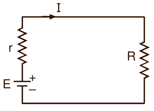
(a) Battery supplying load of R ohms.
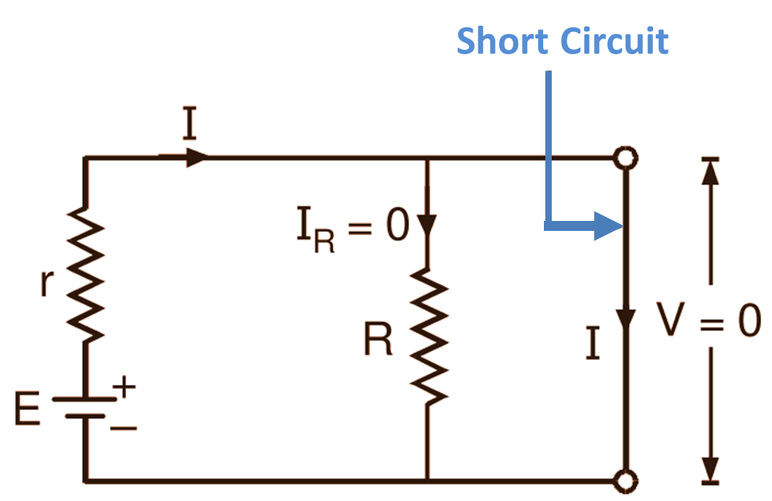
(b) A battery with load short circuited.
Fig. 1: Short Circuit.
In the circuit of Fig. 1 (a), it is obvious that circuit current
\[\text{I }=\text{ }\frac{\text{E}}{\text{r + R}}\]
Now, if a short circuit is established across the resistor of R ohms as shown in Fig. 1 (b), then under this condition, the total resistance of the circuit, RT
\[{{\text{R}}_{\text{T}}}\text{ }=\text{ }\frac{\text{R}\times \text{0}}{\text{R + 0}}\text{ = r ohms}\]
Circuit current will be
\[\text{I }=\text{ }\frac{\text{E}}{{{\text{R}}_{\text{T}}}}\text{ }=\text{ }\frac{\text{E}}{\text{r }}\text{ amperes}\]
If the internal resistance (r) of the battery is very small, then this current will be very high.
Further, since the current always prefers the path of least resistance, all this current will follow the short circuited path and no current will flow through the resistor R. The current will be
\[{{\text{I}}_{\text{R}}}=\text{ }\frac{\text{0}}{\left( 0+\text{R} \right)}\text{ }\times \text{ I }=\text{ 0}\]
Also the resistance of a short circuit being zero ohms, the potential difference across its terminals is always zero volts (since, in accordance with Ohm’s law, V = I × 0 = 0 volts).