In this topic, you study Lap Winding – Definition, Theory, & Diagram.
In lap winding, the start end (S) and finish end (F) of the coil of an armature winding terminate on two adjacent commutator segments respectively (see Figure “1). When the start end terminates on a commutator segment and the finish end terminates on the next forward segment, it is called a progressive lap winding. If the finish end terminates on a segment before the start end segment, it is called a retrogressive lap winding. In lap winding, the number of parallel paths A is equal to the number of field poles P i.e., A = P.
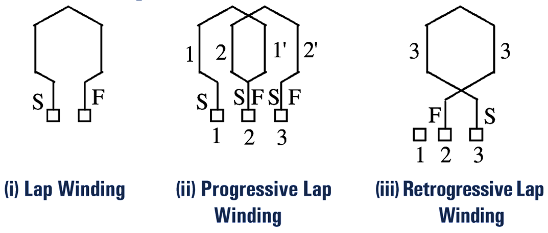
Fig. 2.
In this type of winding, the two ends of each armature coil are connected to adjacent commutator segments. The coils used may be single-turn or multi turn (Fig. 2).
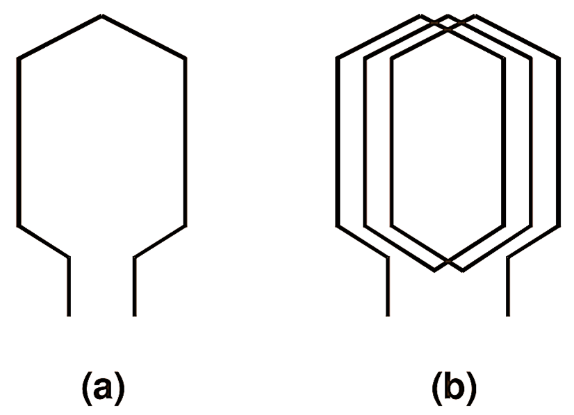
Fig. 2 : (a) Single-turn coil, lap winding, (b) Multi-turn coil, lap winding.
Fig. 3 (a) shows the developed view of a part of simple lap winding using single-turn coils. From this developed view, it will be observed that in this case the starting end of first coil is connected to Segment-l, while its finishing end is brought back to Segment-2. To the same segment is also connected the starting end of the adjacent coil and its finishing end is connected to Segment-3 and so on, each coil being connected between the adjacent commutator segments. This winding derives its name from the fact that successive coils overlap each other.
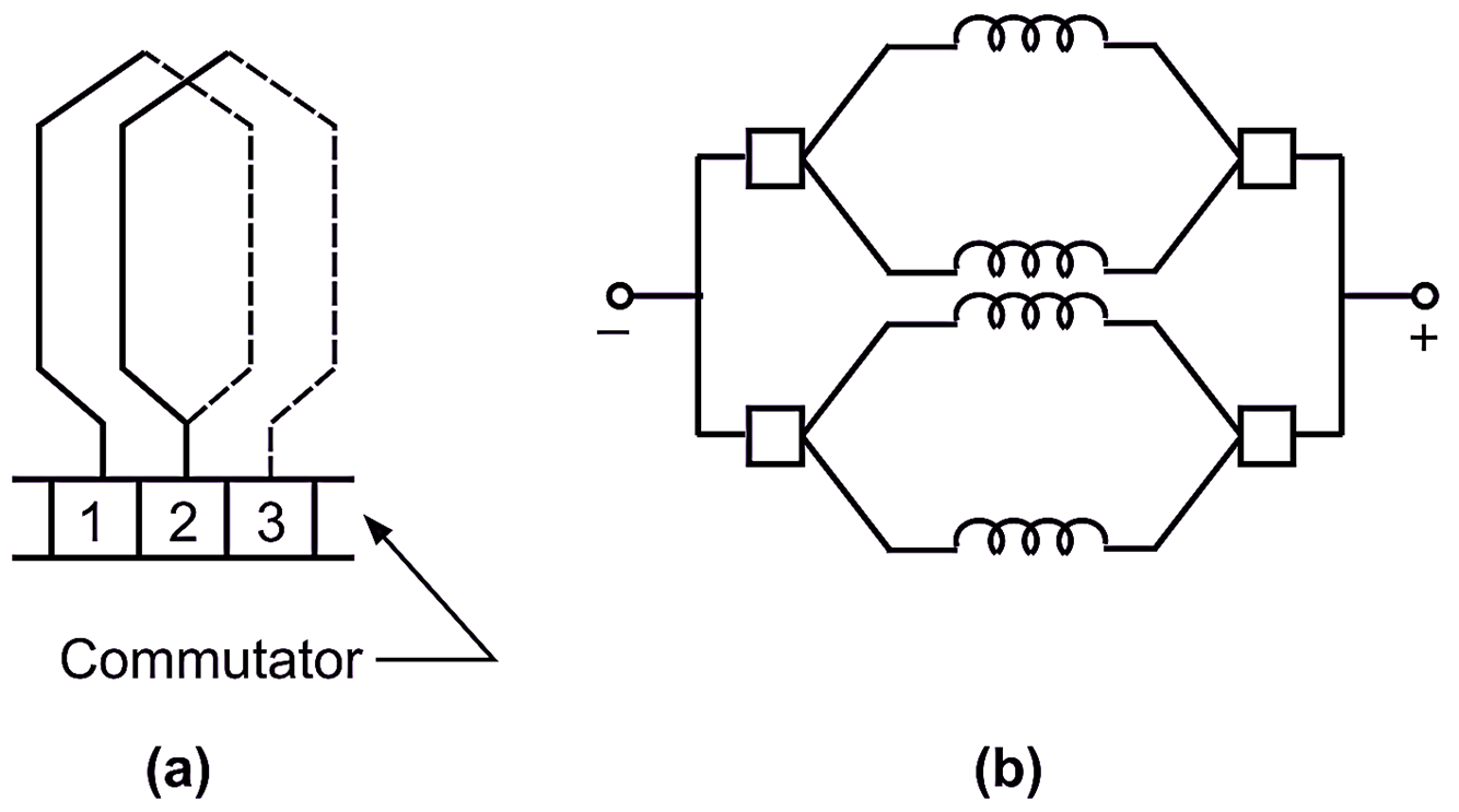
Fig. 3 : (a) Developed view of a part of simple lap winding, (b) Equivalent circuit, lap winding, 4-pole machine.
General Characteristic Features of Lap Winding
Following are some of the important characteristic features of the lap winding:
- The total number of brushes required is equal to the number of poles.
- A lap winding has as many paths (or circuits) in parallel between the negative and positive brushes as the number of poles. Due to this typical characteristic of the lap winding. it is also known as multiple circuit or parallel winding. Fig. 2 shows the equivalent circuit for lap winding in the case of a 4-pole machine.
- The total e.m.f. of the machine is equal to the e.m.f. generated in any one of the parallel paths.
- The total current output divides equally among the different paths in parallel.
Equalizing Connections in Lap Windings
In actual practice, due to magnetic imbalance, the e.m.f.s induced in the various parallel paths of a lap winding are not exactly equal. Under such condition, the resultant e.m.f. acting round the armature may cause large circulating current even when no current is being delivered by the generator. To relieve the brushes of this circulating current, several points on the armature winding which should be at the same potential under ideal conditions are connected together by heavy copper bars to provide permanent paths for these currents. The connections between the different equipotential points are. therefòre. called equalizing connections. These connections are usually in the form of copper rings called equalizer rings.
It should be noted that equalizer connections are provided only in a lap winding. In the case of a wave winding with only two parallel paths, any magnetic imbalance affects the e.m.fs in both the parallel paths equally. Therefore, no equalizing connections are necessary.