In this topic, you study Construction of DC Generator.
The main parts of a DC generator are
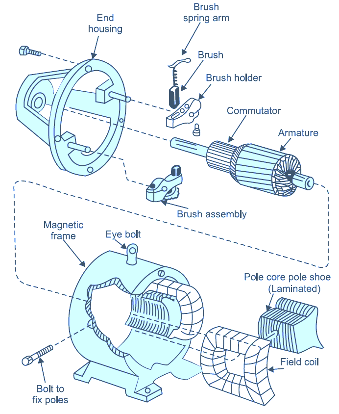
Figure. 1: Parts of DC Generator.
Fig. 2 shows a cross-section of a typical 4-pole dc generator with its main parts labelled. It essentially consists of a stationary part generally referred to as field sytem and the rotating part generally referred to as armature.
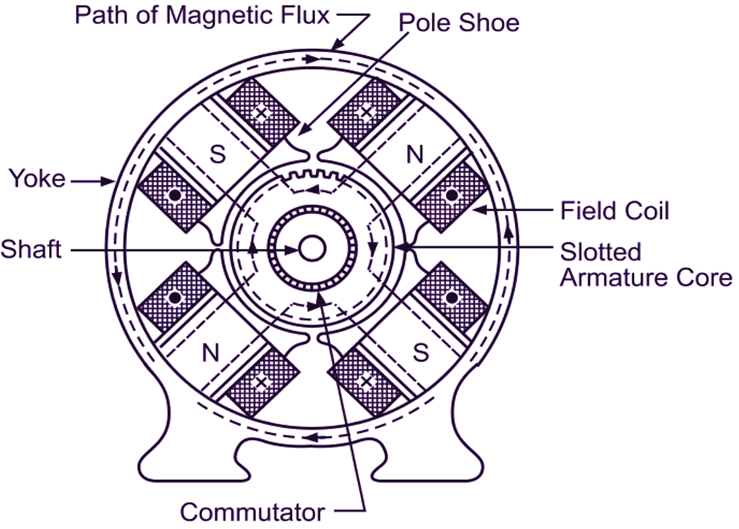
Fig. 2: A cross-section of a typical dc machine
Field System
In almost all the practical dc generators (except very small ones fitted with the permanent magnets). the magnetic field is produced electromagnetically. In these generators. the field system as a whole consists of following components :
Yoke: The main frame of the machine is called the yoke. The yokes may be of cast iron or cast steel for small machines. but for large machines, they are fabricated from rolled steel having higher permeability and better mechanical strength. The yoke serves the following two purposes :
- It supports the other components such as poles and provides mechanical protection for the whole machine.
- It forms a part of the magnetic circuit and provides the path of low reluctance for the magnetic flux.
Field Poles: Each field pole consists of a pole core and its exciting winding called the field coil.
Pole Cores: These are usually made of steel plates rivetted together under hydraulic pressure and bolted to the yoke. Laminated construction is used to reduce the eddy current loss. Each pole core has an extension at one end with a large cross-section known as pole shoe. The pole shoes serve two purposes :
- They support the field coils,
- Being of larger cross-section. they reduce the reluctance of the magnetic path and spread out the flux in the air gap over a large portion of the armature periphery.
Field Coils: The field coils are usually former wound with cotton covered enamelled copper wire. After drying in a vacuum and impregnating with an insulating compound, these coils arc then mounted on (the pole cores. When current is passed through these coils, the field poles work as electromagnets and produce the magnetic flux necessary for generator action. All the field coils are connected in series and referred to collectively as the field winding of a generator. These field coils are so connected that alternately N and S poles are formed.
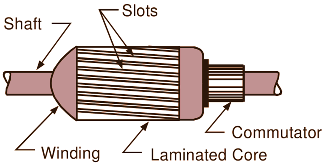
Armature Assembly
The armature assembly usually is made tip of a shaft. armature core, armature winding and commutator (Fig. 2 a).
(a)
(b)
Fig. 2: (a) Armature assembly of a dc generator. (b) Single circular lamination
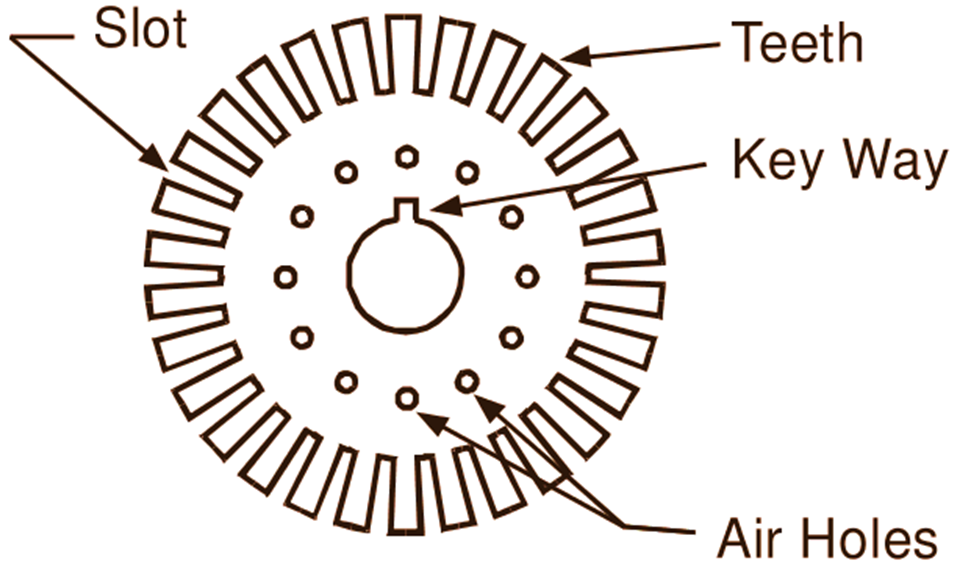
Armature Core: The armature core is a cylindrical structure built up of circular steel laminations (Fig. 2 b) having thickness of about 0.35 to 0.5 mm and insulated from each other by a thin layer of paper or varnish. Use of laminations keep the eddy current loss to a low value. The build-up armature core has a series of longitudinal slots on its periphery for housing the conductors of the armature winding and may have radial and axial air ducts for cooling purposes. It should the remembered that the armature core not only serves the purpose of housing the armature winding hut also provides the path of low reluctance to the magnetic flux.
Armature Winding: The armature winding consists of a large number of coils suitably connected together. These coils are usually wound separately on suitable formers with cotton covered enamelled copper wire and then placed in the core slots lined with tough insulating material. Special hard wooden or fibre wedges are used to prevent the armature conductors from flying out from slots under the action of centrifugal forces during the rotation of the armature. We know that when the armature rotates between the field poles. it is the armature winding where the useful e.m,f. is produced due to flux cutting by its conductors.
Commutator: The commutator is made of wedge-shaped segments of hard-drawn or drop forged copper with V-grooves. These segments are insulated from one another by thin layers of mica and held together by steel V-rings or clamping flanges. These V-rings are insulated from the segments using two cone-shaped collars or rings of built-up mica. The commutator segments may have small longitudinal slits at one end for soldering the leads from the armature coils or may have risers for that purpose. Fig. 3 shows a sectional view of the commutator.

Fig. 3: A sectional view of the commutator
The function of the commutator is to facilitate the collection of current froiiì the armature conductors. It is the commutator that converts the alternating current induced in the armature coils into undirectional current as it enters the external circuit.
Miscellaneous Parts
Brush Assembly: Brushes are used to conduct the current from the commutator to the external circuit. These brushes are usually made of carbon or copper and held in place by the brush holders. For proper contact, each brush is pressed on the commutator surface by a spring and is free to slide in its holder in order that it may follow any irregularities in the commutator. A flexible braided conductor called a pig tail is used to connect the brush to the external circuit. Fig. 4 shows the complete brush assembly.
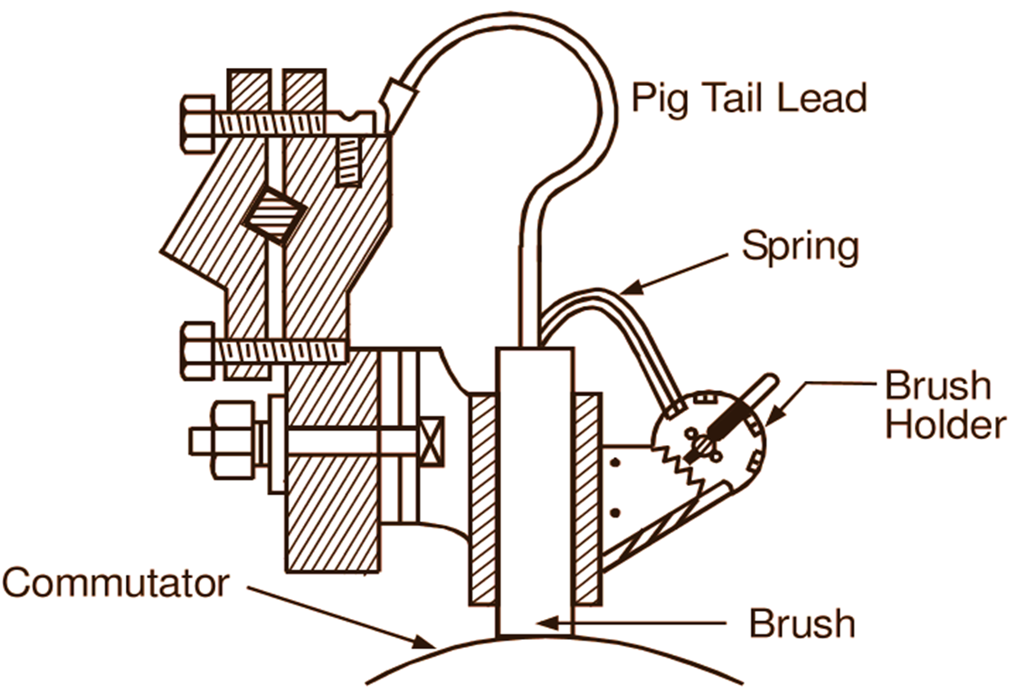
Fig. 4: Brush assembly
Cooling Fan: In some machines, a fan is fitted to the shaft on the side opposite to that of the commutator for cooling purposes.
End Covers: These are attached to the ends of the main frame and contain bearings for the armature. The end cover on the commutator side also supports the brush assemblies.