In this topic, you study Double Revolving Field Theory.
When a single-phase stator winding is connected to a source of alternating voltage, the current flowing through this winding produces a field which varies sinusoidally with time along a fixed space axis. According to double revolving field theory, such a flux can be resolved into two equal sinusoidal fields rotating in opposite directions at synchronous speeds, each having a maximum value equal to one half that of the given field as illustrated in Fig. 1 (a).
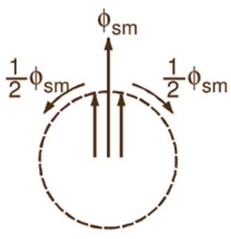
(a)
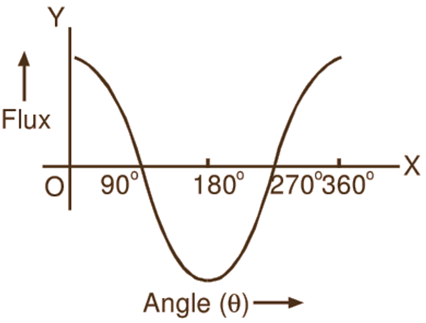
(b)
Fig. 1 : (a) Single-phase alternating stator field represented by two oppositely rotating fields, (b) Resultant of two oppositely rotating fields
Here ɸsm, is assumed to be the maximum value of the stator field ɸs, From Fig. 1 (b), it can be easily verified that the resultant of these two component fields gives the original alternating stator field. Each of the component rotating fields of the stator field produces a torque in opposite directions. The total torque developed by the motor is given by the resultant of these two torques. The complete torque-speed curves (extended into the other quadrant) for the two oppositely rotating component fields considered independently are shown with the help of dotted lines in Fig. 2. The resultant torque-speed curve (solid line) given by the sum of the two component curves is also shown in the figure. From this resultant torque-speed curve, it can be observed that at starting when the rotor is at standstill, the torques developed by two component rotating fields are exactly equal and opposite. Therefore, the torque developed by the motor is zero. Consequently, the single-phase induction motor is not self-starting. However, if the rotor is given an initial rotation in any direction, the net torque developed causes the rotor to continue to rotate in the direction in which it is initially rotated and the motor gives the same type of performance induction motor.
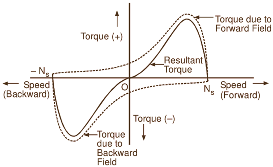
Fig. 2: Torque-speed curves for the two oppositely rotating component fields and resultant torque-speed curve in a single-phase induction motor