In this topic, you study Linear Induction Motor – Construction, Diagram, Working Principle, Applications & Characteristics.
Linear induction motor is a special type of induction motor designed to provide linear motion, based on the principle “whenever a relative motion occurs between field and short circuited conductors, currents are induced and result in electromagnetic forces fùrther which moves conductor in opposite direction”.
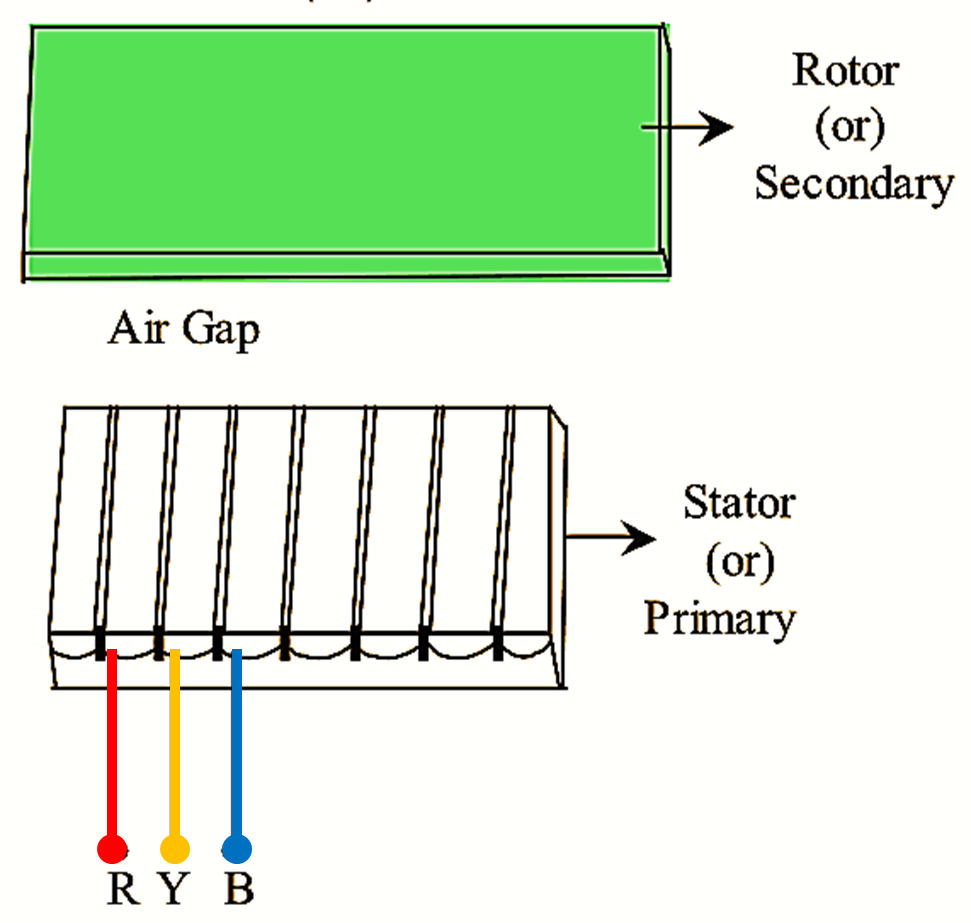
Figure 1: Linear Induction Motor.
Linear induction motor consists of a stator and a rotor with both as movable parts. The stator and rotor are separated by an air gap. Usually stator is known as primary and rotor is known as secondary. The stator consists of a magnetic core with a three phase winding placed in slots and the rotor is a metal sheet made either of Copper (or) Aluminium. The sectional view of a linear induction motor is shown in Figure 1.
Constructional Features of Linear Induction Motor
Linear induction motor is essentially a special type of a polyphase induction motor with its stator (primary) and rotor (secondary) cut by a radial plane and then unrolled (Figs. 2 (a) and (b)) so that instead of producing a torque (causing rotation), it produces a linear force (causing linear motion) along its length. In principle, there are as many different types of linear electric motors as there are rotary electric machines. However, induction type linear electric motors are the most popular one.
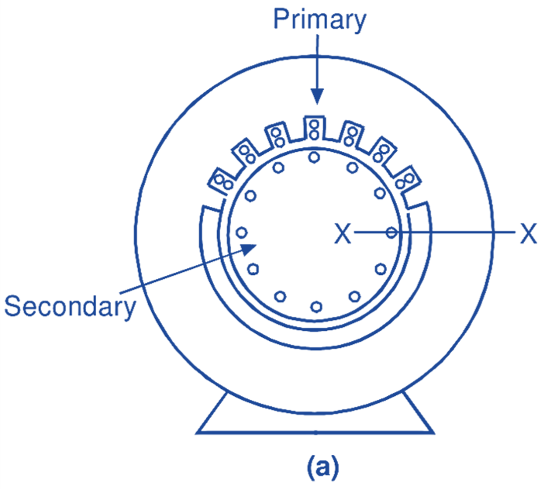
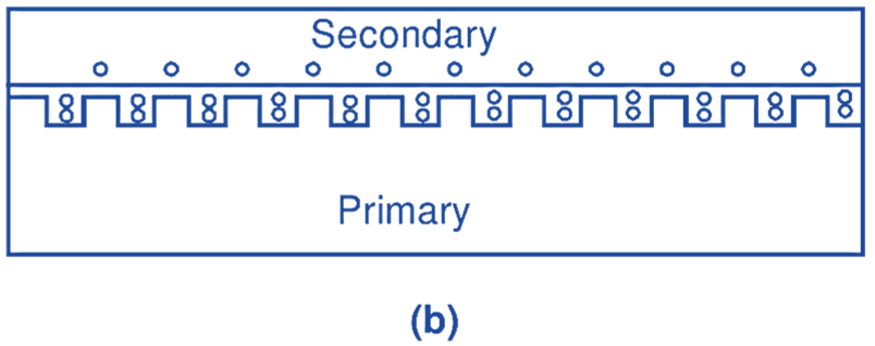
Fig. 2: (a) A conventional cage-type three-phase induction motor in cylindrical form, (b) Primitive linear induction motor.
In its simplest form, a linear induction motor consists of a field system having a three-phase distributed primary winding housed in slots. The field system may have one primary or two primaries as shown in Figs. 3 (a) and (b) or (c) and (d) respectively. Linear induction motor having one primary is called single-sided linear induction motor (SLIM) whereas linear induction motor having two primaries is known as a double-sided linear induction motor (DSLIM). The secondary of a linear induction motor is normally in the form of a conducting plate made of either copper or aluminium. In single-sided linear induction motor, a ferromagnetic plate is generally placed on the other side of the conducting plate to provide a low reluctance path for the main flux. Depending on the use, the linear induction motor may have a short primary (Figs. 3 (a) and (b)) or a short secondary (Figs. 2 (c) and (d)). Unlike a polyphase induction motor, a linear induction motor may have moving primary with fixed secondary or moving secondary with fixed primary.
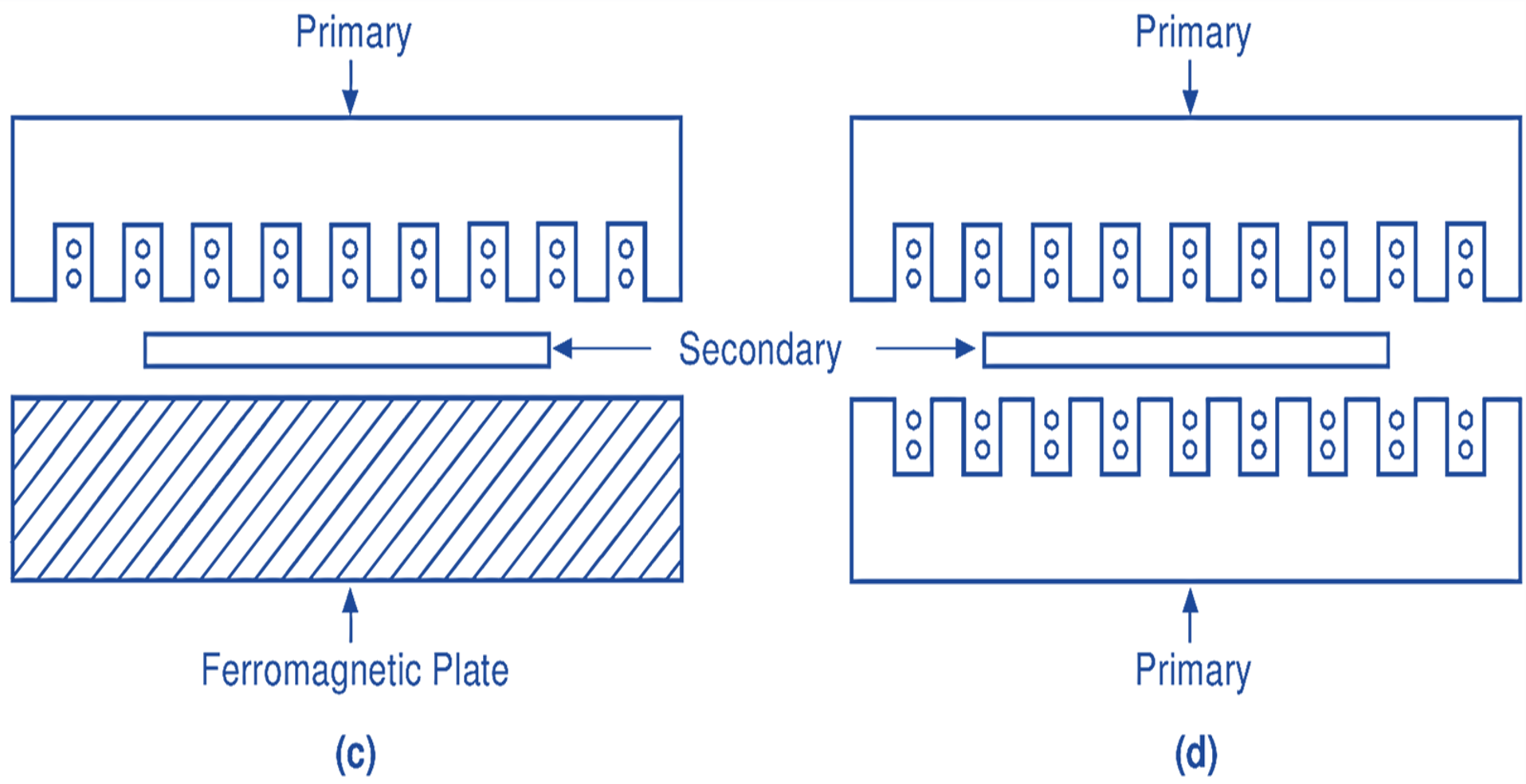
Fig. 3: Diagrammatic representation Of (a) Single-sided linear induction motor with short primary, (b) Double-sided linear induction motor with short primary, (c) Single-sided linear induction motor with short secondary, (d) Double-sided linear induction motor with short secondary
Principle of Operation of Linear Induction Motor
When the primary winding of a linear induction motor is excited from a balanced three-phase supply, a linearly travelling field is produced. The velocity (linear) of this field is given by
\[{{\text{v}}_{\text{1}}}\text{= 2f}\left( \text{pole-pitch} \right)\text{ = f}\lambda \text{ meters/s}\]
where $\text{ }\!\!\lambda\!\!\text{ }$ is the wavelength of the travelling field and is equal to two pole pitches.
This linear travelling field induces eddy currents in the secondary. The interaction between the primary and secondary fields result in the production of the linear force, thus forcing the secondary (if movable) away from the primary and carrying it along in the direction of the linearly travelling magnetic field. As in the case of a conventional induction motor, the velocity (linear) with which the secondary moves is less than ${{\text{v}}_{\text{1}}}$and is given by
\[\text{v }\text{ }\!\!~\!\!\text{ }\text{ = }{{\text{v}}_{\text{1}}}\left( \text{l – S} \right)\text{ meters/s}\]
Thrust-Speed Characteristics of Linear Induction Motor
In the case of a linear induction motor, a force producing the linear motion is called thrust. The thrust-speed characteristic of a linear induction motor is as shown in Fig. 4. It is similar to the torque-speed characteristic of a conventional induction motor.
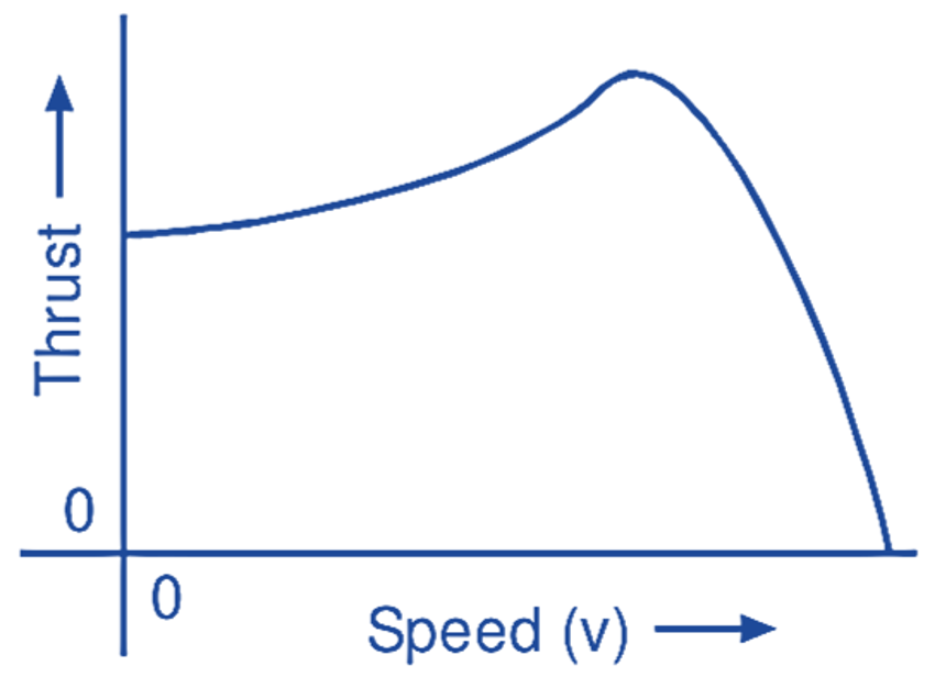
Fig. 4: Thrust-speed characteristic of a linear induction motor
Applications of Linear Induction Motor
There are numerous applications of linear induction motors. Some of them are as listed below:
The aircraft launch system, weaponry, roller coasters, shuttle propulsion, stop valves, induction stirrers for molten metals, automatic sliding doors in electric trains, conveyors, hauliers, electromagnetic pumps, travelling cranes, high-speed traction, accelerating cars and lorries for indoor crash tests, actuators for h. v. circuit breakers, impact extruders for metals, etc.