A McLeod Gauge is a scientific instrument used to measure very low pressures (in the range of 10⁻² to 10⁻⁶ Torr) in vacuum systems. It operates based on Boyle’s Law, which relates the pressure and volume of a gas.
McLeod gauge is a device used for the measurement of very low pressure. McLeod gauge comprises a system of glass tubing, in which, a known volume of gas at unknown pressure is trapped and then isothermally compressed by rising mercury column. This amplifies the unknown pressure and allows its measurement by conventional manometric means. It can measure the pressure of gas, which obeys the Boyle’s law i.e. P1V1 = P2V2.

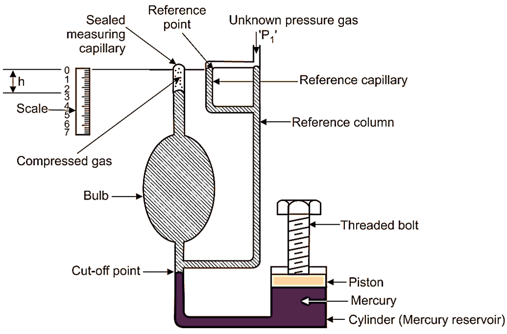
Fig. 1: McLeod Gauge
Construction of McLeod Gauge
The McLeod gauge consists of the following main components:
- Bulb (Gas Reservoir): A large chamber that collects the gas from the system under measurement. Its volume is known and fixed.
- Sealed Measuring Capillary: A narrow tube calibrated with a scale to measure the height () of the mercury column. It used to determine the pressure of the compressed gas.
- Reference Capillary: Provides a reference for measuring the height of mercury.
- Reference Column: A U-shaped column connected to the mercury reservoir and the reference capillary. It balances the mercury levels during operation.
- Mercury Reservoir (Cylinder): Contains mercury, which acts as the compression fluid. The mercury is moved into the bulb and capillary by adjusting the threaded bolt.
- Threaded Bolt: Used to raise or lower the mercury level in the reservoir. It allows precise compression of the gas in the bulb and capillary.
- Scale: Calibrated to directly measure the height (h) of the mercury column in the capillary. It used to calculate the pressure of the gas.
- Cut-off Point: Ensures that a fixed volume of gas is trapped and compressed during operation.
Working of McLeod gauge
The unknown pressure (P1), which is to be measured, is connected to point as shown in Fig. 1.
Piston lifted upwards
Plunger or piston is withdrawn (i.e. lifted upwards) so that, mercury level in all columns and capillaries is lowered. This withdrawal of piston continues till the mercury level gets lowered up to cut-off point. This leads to entry of gas of unknown pressure (P1) into the reference column. At the same time, the gas is admitted into the bulb and sealed measuring capillary. When mercury level is lowered up to cut-off point, then known volume of gas is trapped in the bulb and sealed measuring capillary. Let V1 be the volume of the gas admitted into the bulb and sealed measuring capillary. This volume V1 is the volume of bulb and sealed measuring capillary above cut-off point, which is known to us.
Piston pushed downwards
Now, the piston/plunger is pushed downwards in the mercury reservoir/cylinder. Due to this, the mercury level rises above the cut-off point and the gas gets trapped inside the bulb. If the piston/plunger is further pushed downwards, all the gas in the bulb is compressed into the sealed measuring capillary. The plunger motion is continued, until the mercury level in the reference capillary/reference column reaches the zero mark. This zero mark is also called as reference point. This condition of system is shown in the Fig. 1, indicating mercury levels in all the columns/capillaries by shaded area. Under this condition, the compressed gas volume sealed into the measuring capillary can be read directly in terms of height h. This height ‘h’ also represents the rise in gas pressure in terms of height of mercury column. Therefore, if the initial unknown pressure head is P1, then final pressure head will be,
P2 = P1 + h … (1)
Volume of gas entrapped = Cross-sectional area of measuring capillary × h
Thus,
V2 = a × h … (2)
Thus, value of volume ‘V2’ of gas after compression is calculated, by using Equation 1.
According to Boyle’s law,
P.V = C
P1V1 = P2V2
P1V1 = (P1 + h)V2 [From eq. (1)]
P1V1 = P1V2+ hV2
P1(V1 – V2) = hV2
Thus,
\[{{\text{P}}_{\text{1}}}\text{ }\!\!~\!\!\text{ =}\text{ }~\frac{\text{h}{{\text{V}}_{\text{2}}}}{\left( {{\text{V}}_{\text{1}}}\text{- }{{\text{V}}_{\text{2}}} \right)} ….(3)\]
Since, the values of V1, V2 and h are known, we can determine the value of unknown pressure ‘P1’ using equation (3).
Thus, we say that,
1. For greater amplification ratio, should be large and it can be achieved by,
- Making the size of bulb as large as possible.
- Making the Cross-sectional area of capillary as small as possible.
2. Unknown pressure is computed by physical dimensions of instrument; hence it is used to calibrate low pressure gauges.
Advantages of McLeod Gauge
- Unknown pressure is calculated ¡n terms of physical dimension of instrument. Therefore, it is used to calibrate low pressure gauges.
- It can be used for pressure measurement of all gases. It is not influenced by composition of gas.
- It is used as pressure standard ¡n the range from 1 mm of mercury above absolute zero to 0.01 micron with calibration uncertainty of 0.5
- There is no lower limit to measure low pressure. Any low pressure can be measured.
Disadvantages of McLeod Gauge
- It does not give continuous output.
- It cannot be used, where use of mercury is objectionable.
- It cannot be used for gases with moisture.
Applications of McLeod Gauge
- For Measurement of low pressure.
- For calibration of low-pressure gauges.