The RLC Bridge is the single bridge which can be used for measurement of all the three parameters viz., resistance, inductance and capacitance.
It consists of signal source (ac or dc) and a detector along with following inbuilt bridges:
- Wheatstone Bridge: For measurement of resistance.
- Maxwell’s or Hay Bridges: For measurement of inductance.
- De Sauty Bridge: For measurement of capacitance.
A centre zero milli-ammeter (25 mA – 0 – 25 mA) is used to indicate the balance condition of the bridge. There is also a provision of connecting external supply source and detector.
Laboratory Type RLC Bridge
Schematic circuit of a skeleton type RLC bridge and its accessories is shown in Fig. 1. In this, R3 is decade resistance box. The other arms are completed by connecting the unknown and standard components between terminals 1 – 2, 3 – 4, 7 – 8, 9 – 10 and 11 – 12, a null detector between 5 – 6 and power supply between 13 – 14. The bridge can be used for dc as well as ac measurements. For dc measurements, 1.5 – 7.5 V batteries are used between terminals 13 – 14. A centre zero (25 mA – 0 – 25 mA) milliammeter is used between terminals 5 – 6 as detector.
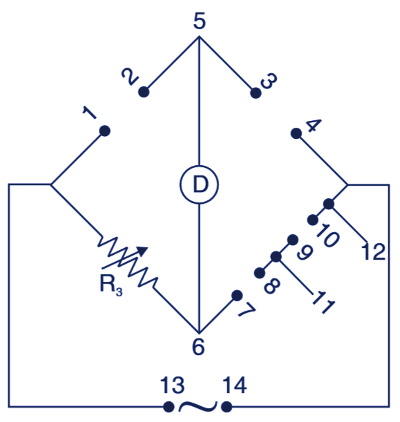
Fig. 1. RLC bridge.
For ac measurements, connect a signal source or oscillator tuned to 1 kHz between terminals 13 and 14 and a null detector (head phone, CRO) between terminals 5 and 6. The Bridge can be used to measure resistance from 0.1 Ω – 10 MΩ, inductance from 1 μH to 100 H and capacitance from 1 pF to 1,000 μF.
RLC Bridge Applications
For measurement proceed as follows:
For Measurement of Resistance
For this (Fig. 2), set up a Wheatstone bridge as explained below:
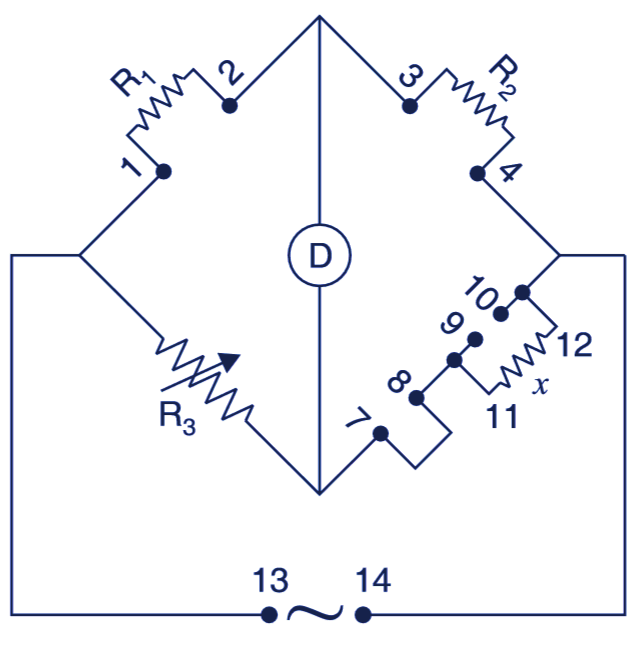
Fig. 2. Measurement of resistance.
- Connect a standard resistance R1 between terminals 1 and 2.
- Connect a standard resistance R2 between terminals 3 and 4.
- Connect the unknown resistance x whose value is to be found between terminals 11 – 12.
- Connect a wire jumper between terminals 7 – 8.
- Keep terminals 9 – 10 open circuit.
- Connect supply between 13 – 14. If supply is dc, use centre zero microammeter as detector and if supply is ac, use ac type null detector.
- Obtain null position by adjusting the decade resistance R3. The value of unknown resistance will be
For Measurement of Inductance
For this (Fig. 3), set up a Maxwell bridge as explained below:
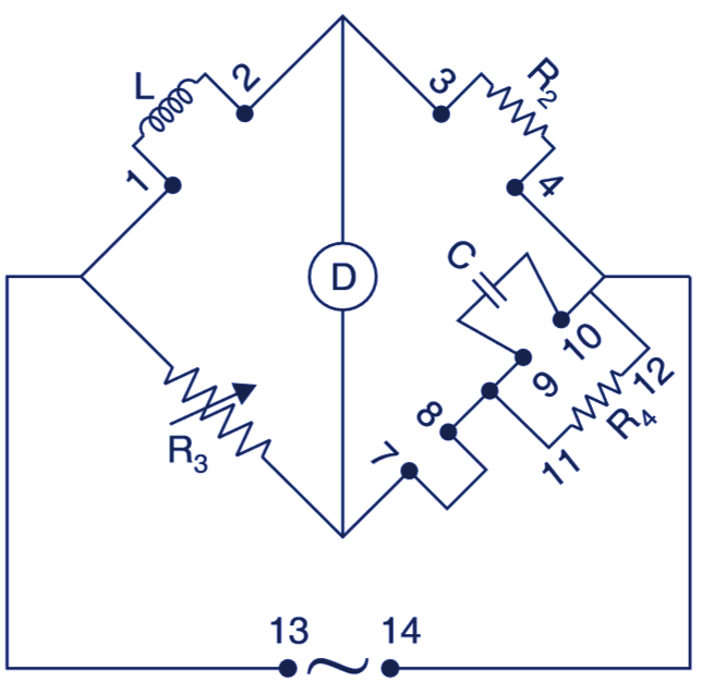
Fig. 3. Measurement of inductance.
- Connect a known capacitor C between terminals 9 – 10.
- Connect a standard resistance R2 between terminals 3 – 4.
- Connect a rheostat R4 between terminals 11 – 12.
- Connect the unknown inductance L, whose value is to be found out between terminals 1 – 2.
- Connect an ac supply between terminals 13 – 14.
- Connect an ac detector D as shown.
- Adjust the decade resistance R3 and the of inductance rheostat R4 to obtain the null position. The value of unknown inductance will be:
L = R2R3C
The L is in henry, R2 and R3 in ohms and C in farad.
For Measurement of Capacitance
For measurement of capacitance (Fig. 4), set up the De Sauty Bridge as explained below:
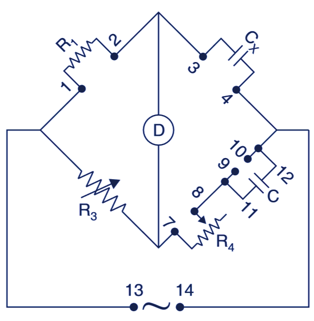
Fig. 4. Measurement of capacitance.
- Connect a standard resistance R1 between terminals 1 and 2.
- Connect a known capacitor C between 11 and 12.
- Connect the capacitance C to be measured between terminals 3 and 4.
- Connect a rheostat R4 between the terminals 7 and 8.
- Connect an ac supply between terminals 13 and 14.
- Connect an ac detector as shown.
- Adjust the decade resistance R3 and find the null position.
- At null (i.e., balanced position), determine the value of unknown capacitor by the following formulae:
The C is in microfarad, R3 and R1 are in ohms.