In this topic, you study Megger – Theory, Construction & Diagram.
As the name indicates, Megger is an instrument, which reads high resistances in Mega ohm (1 MΩ = 106 ohms).
Working Principle of Megger
The principle of working is the same as that of a moving coil instrument, i.e., “a current carrying conductor placed in a magnetic field experiences a torque”.
Construction of Megger
As shown in Figure 1, there are two coils potential (pressure or voltages) coil (P.C.) and current coil (C.C.), which are fixed together and can rotate about a common axis between the poles of a permanent magnet. The R1 and R2 are the resistances to control the amount of current though P.C. and C.C. respectively. A pointer is attached with the moving coil (C.C.), which gives deflection on a scale calibrated in Megahoms (form zero to Infinity). Note, that the current coil also called “deflecting coil” and potential coil as “controlling coil” which provides a control on the movement of the pointer.

Fig. 1: Megger
The dc generator, when driven by hand, generates a voltage between 250 to 2500 V which is used by the instrument for measurement of unknown resistance. The instrument is widely used for measurement of insulation resistance of cables. For this, a terminal G (Guard terminal) is provided. by means of which “guard ring” can be connected to a guard wire on the insulation under test.
Working of Megger
The resistance under test is connected between terminals, Line (L) and Guard (G). Now the generator of the instrument is driven at a uniform speed till the pointer gives a steady reading on the scale (Figure 2). The working of the Megger can be understood in three parts.
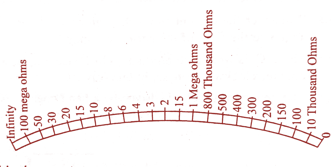
Fig. 2: Megger scale
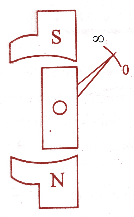
- If the terminals are open i.e., resistance is not connected between L and G, in this case, when the generator is driven it sends current through P.C. but no current flows through the C.C. and the moving system rotates in such a way that the pointer rests on infinity.
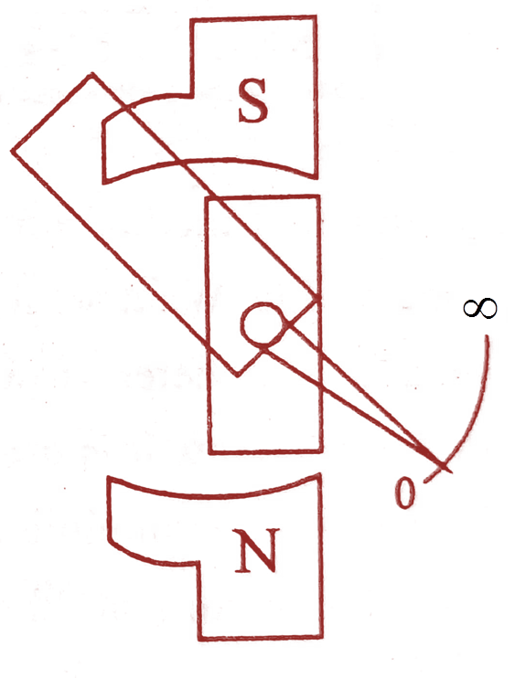
- If test terminals are short circuited by a wire of negligible resistance and the generator is driven, in that case it sends a very large current through CC and very small current through P.C. the resultant torque moves the pointer to zero on the scale.
- If the unknown resistance which is to be measured is connected between L and G on driving the generator, an appreciable current passes through both the coils. Now the position taken up the pointer depends upon the ratio of currents in the two coils i.e., upon the value of unknown resistance. Now the pointer will indicate the value of the resistance connected between L and G.
(a)
(b)
Fig. 3: Open and Short conditions on Megger
Note some points about the Megger
- A compensating coil may be connected in series with the P.C. in order to obtain better scale proportions.
- Whenever the current flows through coils, the P.C. tends to set itself at right angles to the field of the permanent magnet.
- The C.C. is wound to produce a clockwise torque, whereas the P.C. produces a counter clockwise torque, in this way P.C. controls the movements of C.C.
Applications of the Megger
- Checking the insulation resistance of cables.
- Checking the continuity.
Specification of the Megger
In megger. the generator usually is driven by a hand operated Crank and it generates test voltages. And a megger is basically specified based on the voltage generated by it.
For example: 250 V, 500V, 1KV, 2.5KV, 5KV.