In this topic, you study Earth tester or Earth resistance tester – Construction & Diagram.
Earth tester is an electrical measuring instrument used to measure the resistance between any two points of the earth. It is also called as Earth resistance tester (see Fig. 1).
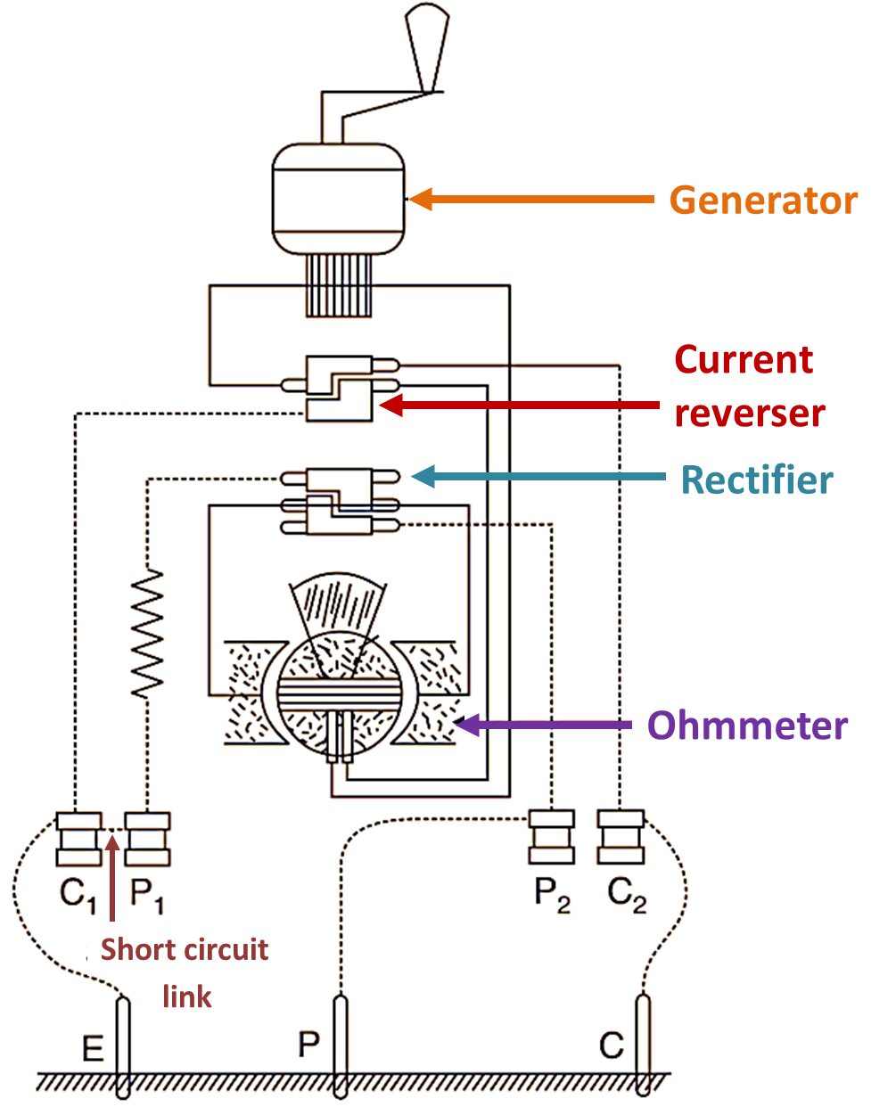
Fig. 1: Earth tester
Construction and Working of Earth tester
As shown in Figure 1, earth tester is a combination of direct reading ohmmeter and a small hand driven DC generator which supplies the testing voltage of about 500 V. The ohmmeter consists of current and potential coils fixed at right angle to each other and constitute the moving system of the earth tester. There is a pointer attached with this moving system, which shows deflection on a calibrated scale. The earth tester has terminals brought outside and marked as P1, C1, P2 and C2. The earth tester is a special type of instrument, which supplies DC to the ohm meter for its proper working and AC to the earth electrodes. The area between the two electrodes in the earth acts as an electrolytic cell (the soil in between behaves as electrolyte). If DC is sent to electrodes, electrolysis may start under earth. For this purpose, the earth tester is provided with a current reverser which converts DC (generated by the hand driven generator) into AC, which is fed to earth. After the alternating current passes through the electrodes, the measurement should be done by an ohmmeter which requires DC supply. And the earth tester is also provided with a synchronous rotatory rectifier which converts the AC again into DC for the ohmmeter.
Earth Resistance Measurement
Earth tester is an electrical measuring instrument used to measure the resistance between any two points of the earth.
How to measure earth resistance using Earth tester (See Fig. 2)
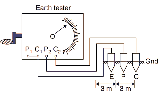
Fig. 2: Use of Earth tester
As shown in Figure 1, to measure earth resistance, the terminals P1 and C1 of the earth tester are short circuited to get a common point. This common point is connected with the main electrode E under test through a wire of negligible resistance. Now, place the two electrodes P and C at a sufficient distance from E. And a distance of above 15 metres between electrode A and C is regarded as sufficient distance. The electrode P is buried about half way between E and C, such as EP = EC = 3 m. The terminal P2 connected with the electrode B and the terminal C2 connected with the electrode C.
The auxiliary electrode P is moved from position P1 and P2 [Fig. 3] respectively so that resistance areas don’t overlap. The hand driven generator is now rotated and thus 3 readings are obtained from the ohmmeter and a mean of the three gives the value of earth resistance.
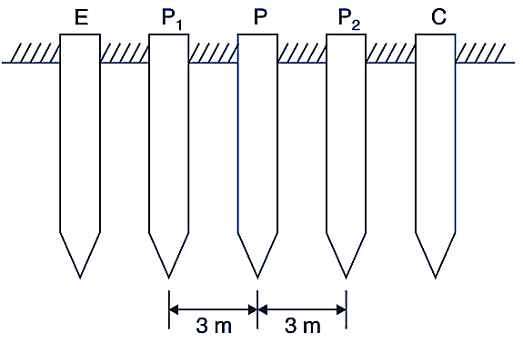
Fig. 3: Burying Electrodes.
Note that the value of earth resistance should be as small as possible. The ideal value of earth resistance is zero, and practically it may be upto 5 Ω. The reason for earth resistance being low is that in case of an earth fault in equipment, the faulty current flows through the earth and the operator does not get shocked (Fig. 3). To maintain the resistance at a low value the surroundings of earth electrodes are kept moist by pouring water from outside. A funnel is provided for this purpose. The earth wire is embedded in the alternate layers of coal dust and salt to maintain the surrounding moist.