In this topic, you study DOL Starter (Direct Online Starter) – Working & Diagram.
Direct on line Starting
In this method, a squirrel cage induction motor is started by connecting it directly to the line i.e. without using any special device for reducing the starting current. However, as said earlier, this method is restricted only to small squirrel cage induction motors.
Direct on line Starter
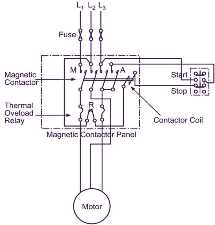
Fig. 1 (a) shows a typical direct on line starter called DOL starter suitable for a small squirrel cage induction motor consisting of a magnetic contactor and thermal overload relay and Fig. 1 (b) shows a schematic wiring diagram for its control circuit. When start push-button is pressed, the contactor coil is energised and its three normally open (N/O) main contacts (M) are closed.
(a)
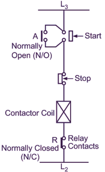
(b)
Fig. 1 : (a) Typical direct on line starter for small squirrel cage induction motor, (b) Schematic wiring diagram for the control circuit
Thus, the motor gets connected across the supply mains. The contactor remains closed even when the start push-button is released because its operating coil continues to get supply through the closed auxiliary or hold-on contacts (A) of the contactor. The motor continues to run until shut down by pressing the stop push-button, by the tripping of the overload relay (meaning by opening of its normally closed contacts R) under overload conditions, or by power failure. From the figure, it will be seen that the thermal overload relay has only two thermal elements. This is because an overload or a break in the phase without thermal element can cause an increased current in the other two phases sufficient enough to actuate the relay. Fuses are provided for the protection of the motor against short-circuits. A single phasing preventer may also be provided for protection against single phasing.
DOL Starter Working Principle
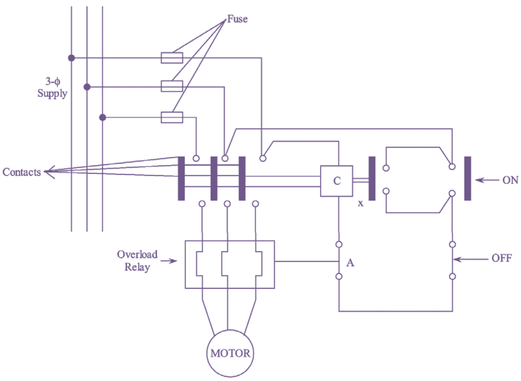
Direct on-line starting (or) full voltage starting involves the direct switching of polyphase stator on to the supply mains i.e., in this method of starting, induction motors can be started directly by connecting the two ends of each phase of the stator terminals to the 3-ϕ supply. This method of starting is only applicable for small size induction motors i.e., upto 3 kW rating.
This method of starting consists of contactor coil, overload relay and fuses to protect the motor from short circuit. The contactor coil energizes and de-energizes when the push button is ON and OFF respectively. The contacts of the contactor which are opened gets closed when the coil energizes i.e., at the time when the push button is ON and through the contacts of the contactor, the motor gets connected to the supply. The hold-on contact ‘x’ also gives supply to the motor and due to this the motor is continuously fed even when the push button is released.
Similarly when the push button is OFF, the contacts of the contactor gets opened when the coil de-energizes and thus the motor stops. The contact ‘A’ of the overload relay opens when the motor gets overloaded. The DOL starter for 3-ϕ induction motor is shown in figure.
DOL Starter Starting Torque in terms of Full Load Torque
Let Ist and Ifl be the per phase stator currents corresponding to starting and full-load conditions respectively. The electromagnetic torque is given by,
\[T=\frac{1}{{{\omega }_{2}}}I_{2}^{2}\frac{{{r}_{2}}}{s}…(1)\]
The ratio starting torque to full load torque is given by,
\[\frac{{{T}_{st}}}{{{T}_{fl}}}=\frac{\frac{1}{{{\omega }_{2}}}I_{2st}^{2}\frac{{{r}_{2}}}{{{s}_{st}}}}{\frac{1}{{{\omega }_{2}}}I_{2fl}^{2}\frac{{{r}_{2}}}{{{s}_{fl}}}}\]
\[=\frac{I_{2st}^{2}\frac{{{r}_{2}}}{1}}{I_{2fl}^{2}\frac{{{r}_{2}}}{{{s}_{fl}}}}\text{ }\left[Slip,{{s}_{st}}=1 \right]\]
\[={{\left( \frac{{{I}_{2st}}}{{{I}_{2fl}}} \right)}^{2}}{{s}_{fl}}…(2)\]
If no load current is neglected
\[\frac{{{I}_{st}}}{{{I}_{2st}}}=\frac{\text{Effective rotor turns}}{\text{Effective stator turns}}…(3)\]
Also
\[\frac{{{I}_{fl}}}{{{I}_{2fl}}}=\frac{\text{Effective rotor turns}}{\text{Effective stator turns}}…(4)\]
From equation (3) and (4), we have
\[\frac{{{I}_{st}}}{{{I}_{2st}}}=\frac{{{I}_{fl}}}{{{I}_{2fl}}}\]
\[\frac{{{I}_{st}}}{{{I}_{fl}}}=\frac{{{I}_{2fl}}}{{{I}_{2fl}}}…(5)\]
Substituting equation (5) in equation (2), we get
\[\frac{{{T}_{st}}}{{{T}_{fl}}}={{\left( \frac{{{I}_{st}}}{{{I}_{fl}}} \right)}^{2}}\times {{S}_{fl}}…(6)\]
If V1 is the stator voltage per phase and Zsc is the leakage impedance per phase referred to stator then, Short circuit current,
\[{{I}_{st}}=\frac{{{V}_{1}}}{{{Z}_{sc}}}\]
In DOL-sta1ter, the shunt branch in the induction equivalent circuit is neglected.
\[\text{For direct switching, }{{I}_{st}}={{I}_{sc}}=\frac{{{V}_{1}}}{{{Z}_{sc}}}\]
Thus, equation (6) can be rewritten as,
\[\frac{{{T}_{st}}}{{{T}_{fl}}}={{\left( \frac{{{I}_{st}}}{{{I}_{fl}}} \right)}^{2}}\times {{s}_{fl}}\]
Also,
\[{{T}_{st}}={{T}_{fl}}\times {{s}_{fl}}{{\left( \frac{{{I}_{sc}}}{{{I}_{fl}}} \right)}^{2}}\]
Advantages of DOL Starter
- Simple in construction.
- High starting torque.
- Economical.
Disadvantages of DOL Starter
- Limited torque for certain types of loads.
- Large inrush current.
Applications of DOL Starter
DOL staffers can be used if the voltage drop in the supply circuit is not excessive due to the high inrush current of the motor. Due to this reason, the size of a motor allowed on DOL staffer may be limited (upto 10 kW). They are widely used to start,
- Compressors
- Fans
- Conveyor belts.
Summary of DOL Starter
1.The staffing current in DOL-starter is equal to short circuit current i.e., Ist = Isc
2. The staffing torque of DOL starter is 1.5-2.5 times of the full-load torque and the ratio of starting to full-load torque is,
\[\frac{{{T}_{st}}}{{{T}_{fl}}}={{\left( \frac{{{I}_{st}}}{{{I}_{fl}}} \right)}^{2}}{{s}_{fl}}.\]
3. It is easy to install, maintain and very simple in operation.
4. It is the most economical and most inexpensive and simplest starter used for starting squirrel cage induction motors.
Control Circuit (Wiring Diagram) of DOL Starter using Relays
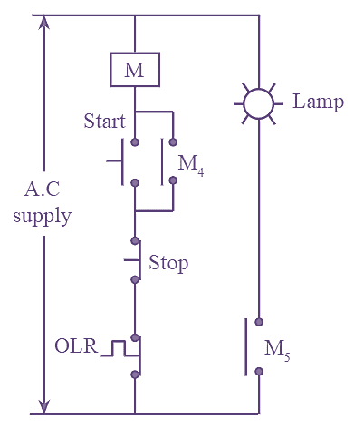
Fig. 2: Control Circuit of DOL Starter
In many industries, DOL staffer (or) direct motor staffer is used to staff A.C motors. The DOL is mainly made up of a 3-phase contactor and an overload relay. The control circuit of DOL starter is shown in above figure (2).
The contactor output (or) coil M gets energized, when the start push button is pressed. The main contacts and auxiliary contacts of contactor coil M gets closed and staff the motor by providing the supply. Due to closing of auxiliary contact coil M5, the supply is given to the lamp. Hence, lamp starts to glow indicating the running condition of the motor. When the contacts of OLR (Overload relay) opens, the motor tums off automatically. The motor can also be turned off by using STOP button. In DOL staffer staff push button, stop push button and NC contact of overload relay are used as inputs and indicating lamp, contactor coil are used as output. The ladder logic diagram of DOL staffer is shown in figure (3).
Let,
Start push button Input – 1
STOP push button – Input 2
NC contact of relay – Input 3
Contactor coil (M) – Output 1
Indicating lamp – Output 2
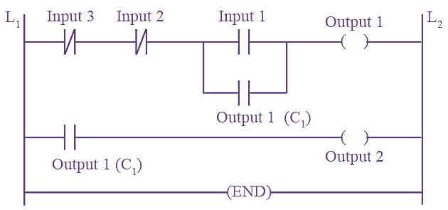
Fig. 3: Ladder logic Diagram of DOL Starter