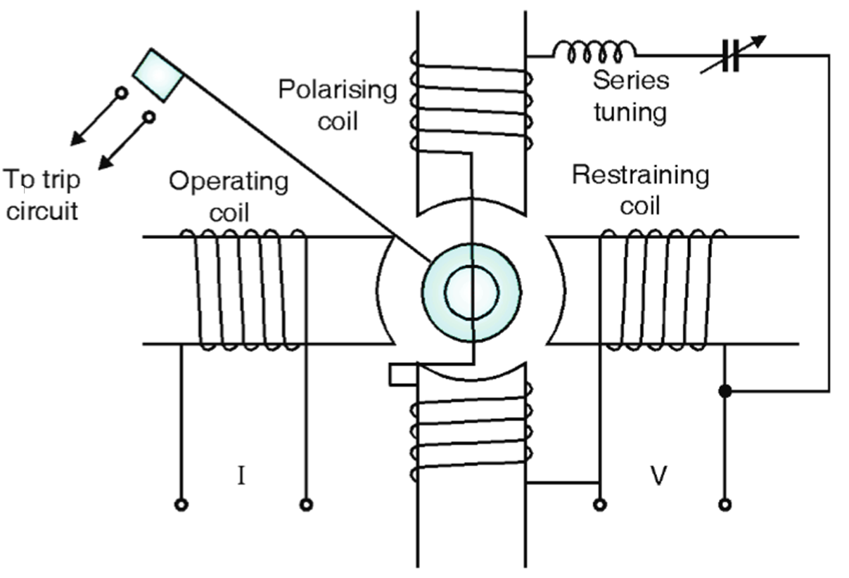
The impedance relay is not normally used because of need of a separate directional unit. So mho type relays are normally used. Working is similar to impedance relay. It is made directional by providing polarising winding so torque produced is polarizing flux times fluxes from (opposed) I and V poles as shown in Fig. 1.

Fig. 1: MHO Relay.
Torque Equation of MHO Relay
The general Torque equation is
\[\text{T }=\text{ }\!\!~\!\!\text{ }{{\text{K}}_{\text{1}}}\text{V I cos}\left( \Phi \text{ }\!\!~\!\!\text{ – }\!\!~\!\!\text{ }\alpha \right)\text{ – }{{\text{K}}_{\text{2}}}{{\text{V}}^{\text{2}}}\text{ – }\!\!~\!\!\text{ }{{\text{K}}_{\text{3}}}\]
where, V = Voltage to relay coil
I = Currcnt to relay coil
Φ = p.f. angle
α = Angle of max. torque
K3 = Constant of relay spring
At the time when relay is on the verge of operation
\[\text{T }=\text{ }~0\]
\[{{\text{K}}_{\text{2}}}{{\text{V}}^{\text{2}}}\text{ }=\text{ }~{{\text{K}}_{\text{1}}}\text{V I cos}\left( \Phi ~\text{ }-\text{ }~\alpha \right)\text{ – }~{{\text{K}}_{\text{3}}}\]
Dividing both sides by K2VI
\[\frac{\text{V}}{\text{I}}=\text{ Z}=\frac{{{\text{K}}_{\text{1}}}}{{{\text{K}}_{\text{2}}}}\text{ cos}\left( \Phi ~\text{ }-\text{ }~\alpha \right)-\frac{{{\text{K}}_{\text{1}}}}{{{\text{K}}_{\text{2}}}\text{V I}}\]
Neglecting the effect of spring K3 = 0
\[\frac{\text{V}}{\text{I}}=\frac{{{\text{K}}_{\text{1}}}}{{{\text{K}}_{\text{2}}}}\text{ cos}\left( \Phi ~\text{ }-\text{ }~\alpha \text{ }\!\!~\!\!\text{ } \right)\]
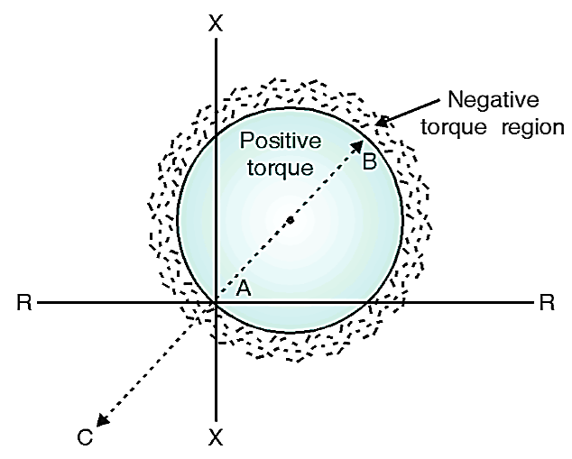
This is the equation of a circle of diameter K1 / K2.
Consider that mho relay is located at point A (Fig. 2). So relay operates only for fault occurring in line AB and it doesn’t operate for faults occurring in AC. Hence, from this operation it is clear that this relay is made inherently directional.

Fig. 2: Characteristics of MHO Relay