Reactance relay is over current relay with directional restraint. The current polarizing flux goes from upper polarizing coil magnet to lower electromagnet through cylinder and iron core. So due to this flux current is induced in the cylinder whose direction is perpendicular to the plane of this paper. And it flows up and down at the sides of cylinder which are opposite of the other two poles (i.e. operating coil magnet pole and restraining coil magnet pole).
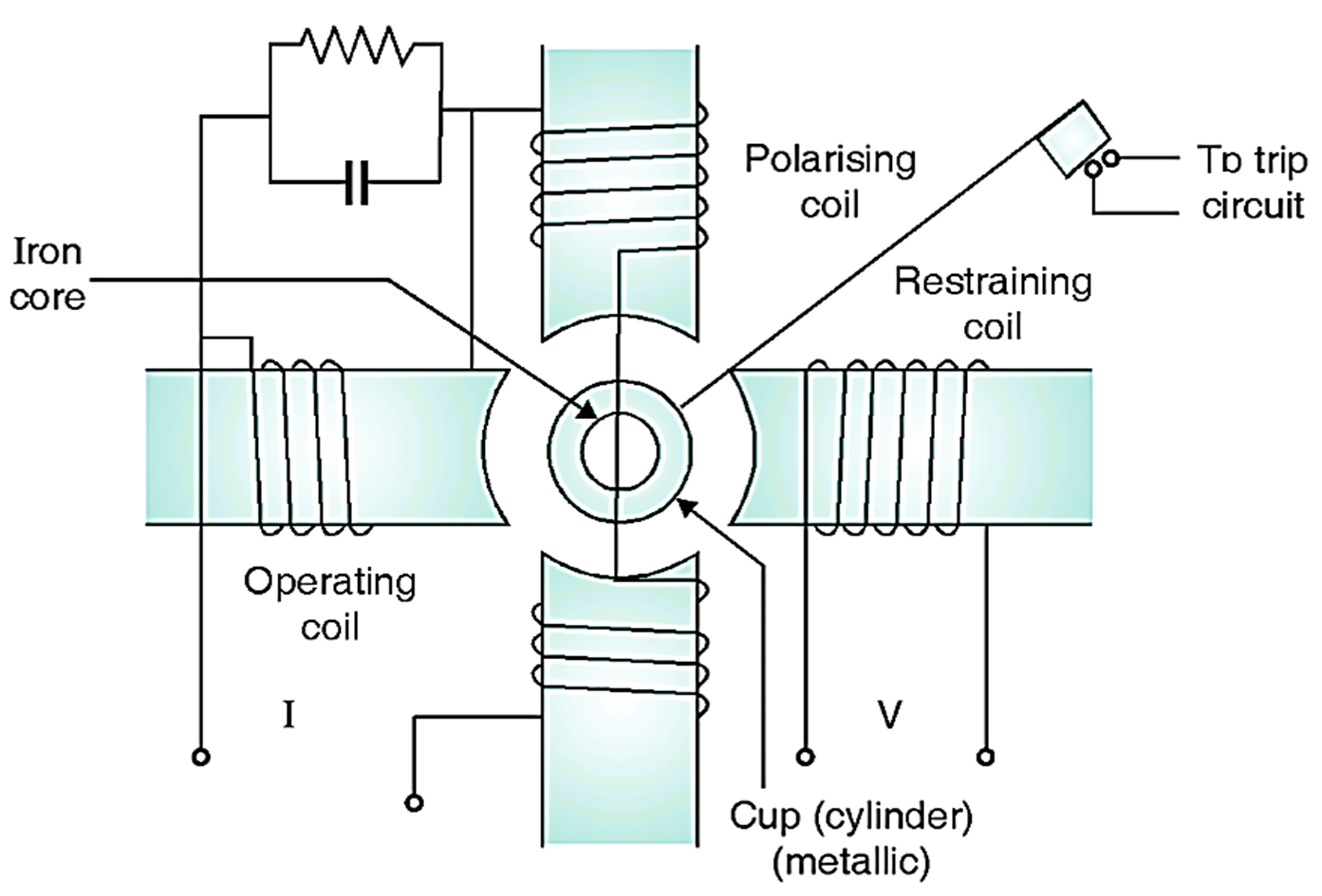
Fig. 1: Reactance relay
The current in cylinder portion which is opposite operating coil pole reacts with the flux of that pole and produces torque ∝ I2 tending to close the relay contacts. And current in the cylinder portion opposite to restraining coil pole reacts with the flux of that pole and produce a torque a VI tending to open the relay contacts
Torque Equation of MHO Relay
The general Torque equation is
\[\text{T}=~\text{ }{{\text{K}}_{\text{1}}}{{\text{I}}^{\text{2}}}\text{ – }{{\text{K}}_{\text{2}}}\text{V I cos}\left( \Phi \text{ }~\text{ }\!\!~\!\!\text{ – }~\text{ }\!\!~\!\!\text{ }\alpha \text{ }\!\!~\!\!\text{ } \right)\text{ – }~\text{ }\!\!~\!\!\text{ }{{\text{K}}_{\text{3}}}\]
where, T = Operating torque
V = Voltage to relay coil
I = Current to relay coil
Φ = Phase angle between V and I
α = Angle of maximum torque
K3 = Spring constant
Angle of maximum torque ‘α’ = 90°
\[\text{cos}\left( \Phi ~-~\text{ }\alpha ~ \right)=\text{ cos}\left( \Phi ~-~\text{ }90~ \right)=\text{ sin }\Phi \]
When relay is on the verge of operation,
\[\text{T }=\text{ }~0\]
\[\text{0}=~\text{ }{{\text{K}}_{\text{1}}}{{\text{I}}^{\text{2}}}\text{ – }{{\text{K}}_{\text{2}}}\text{V I cos}\left( \Phi ~\text{ }-\text{ }\alpha \right)\text{ -}~\text{ }{{\text{K}}_{\text{3}}}\].
\[{{\text{K}}_{\text{1}}}{{\text{I}}^{\text{2}}}=~\text{ }{{\text{K}}_{\text{2}}}\text{V I cos}\left( \Phi ~\text{ }-\text{ }\alpha \right)\text{ -}~\text{ }{{\text{K}}_{\text{3}}}\]
Dividing both sides by K2I2
\[\frac{{{\text{K}}_{\text{1}}}}{{{\text{K}}_{\text{2}}}}\text{ }=\text{ }\frac{\text{V sin }\Phi }{\text{I}}+\frac{{{\text{K}}_{\text{3}}}}{{{\text{K}}_{\text{2}}}{{\text{I}}^{2}}}\]
Neglecting K3,
\[\frac{\text{V}}{\text{I}}\sin \Phi =\frac{{{\text{K}}_{\text{1}}}}{{{\text{K}}_{\text{2}}}}=\text{X}\]
T sin Ø = = X where, X = reactance of potential circuit.
K1 / K2 = X so relay operates on reactance only.
So operating characteristic is a vector whose head lie on the characteristic such that it has a constant magnitude of X as shown in Fig. 2.
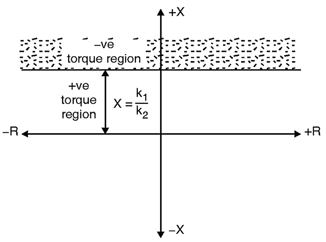
Fig. 2: Characteristics of Reactance Relay