Load in Parallel with the SCR
The class A commutation is also called as self commutation. Fig. 1 shows the SCR circuit that uses a class A commutation. In Fig. 1, L and C are the commutating components and R is the load resistance. The commutation components L and C form an underdamped resonant circuit. Various voltage and current waveforms and equivalent circuits are shown in Fig. 2.
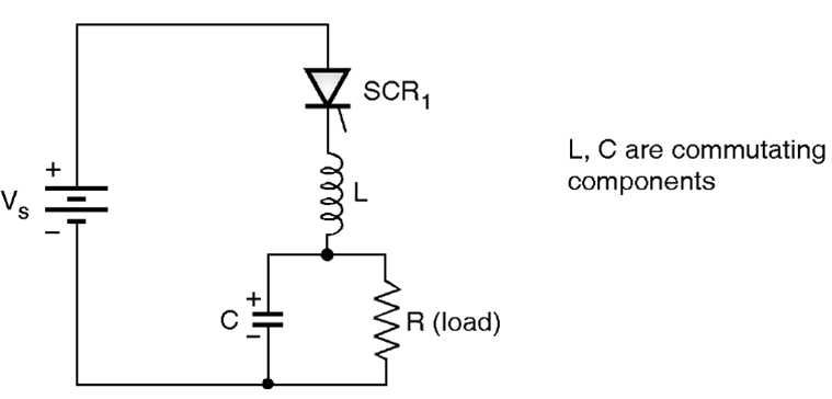
Fig. 1: Self commutation circuit (class A)
Operation of the circuit:
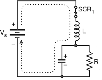
Refer to Fig. 2 (a). At t = t0 the SCR1 is turned on, the dc supply voltage is applied to the resonant circuit.
(a)
(b)
(c)
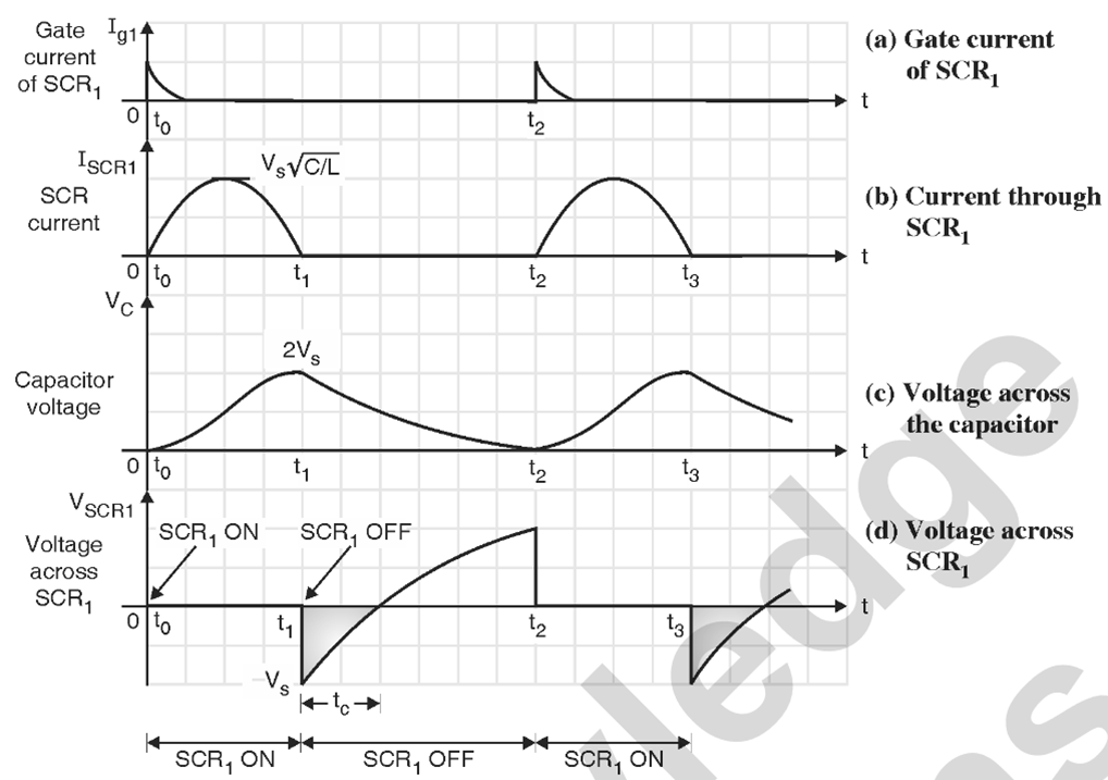
Fig. 2: Waveforms and equivalent circuits for self commutation (class A) circuit.
Due to the presence of underdamped LC resonant circuit, the anode current of SCR1 is sinusoidal in nature (see Fig. 2(b)). This current will charge the capacitor C with its upper plate positive with respect to its lower plate.
At t = t1 the voltage on capacitor C reaches its maximum and the anode current goes to zero. The capacitor will then attempt to force a reverse current through SCR1 which turns off due to net anode current going to zero. In this way, the class A commutation is “current commutation”. As soon as the SCR1 is turned off, the capacitor C starts discharging through R (see Fig. 2(c)). The voltage across SCR1 at the instant t1 is negative as the voltage on the capacitor C is higher than the input supply voltage VS. The voltage across SCR1 then gradually increases towards zero as the capacitor discharges and finally reaches the positive supply voltage level + VS when C is completely discharged. The voltage across SCR1 is nearly zero from t0 to t1 when it is conducting. The time period tC shown by shaded portion in Fig. 2(b) is called as circuit turn off time. It is the time for which the commutated SCR is reverse biased. For successful commutation, tC should be greater than or equal to the SCR turn off tq. At instant t2, the SCR1 is turned on again and the operation repeats itself.
Load in Series with the SCR
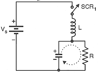
This is another arrangement of class A type commutation. It is shown in Fig. 3 and the load is connected in series with L and C.
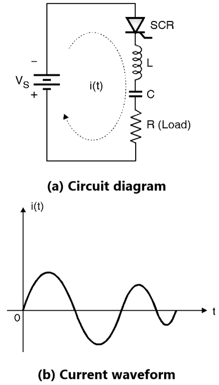
Fig. 3: Class A commutation with load in series with the capacitor
Operation
When the SCR is turned on by applying a gate pulse, the charging current i(t) of the capacitor starts flowing. As the LC components form an under damped circuit, the charging current will be sinusoidal in nature. As soon as the capacitor is fully charged, the charging current reduces to zero and the SCR is turned off due to natural commutation