In this topic, you study Polarity Test of Transformer.
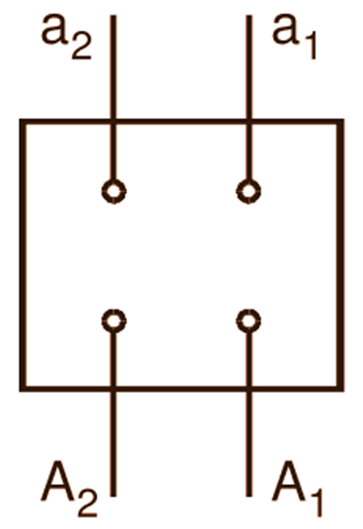
In a transformer, each of the primary terminals becomes alternately positive and negative with respect to the other. The same is true about the secondary terminals. If the transformer is to be used alone, the instantaneous polarities of its terminals are not important. But if the transformers are to be operated in parallel or are to be used in a polyphase circuit, the Relative polarities of the primary and secondary terminals at any instant for each transformer must be known. This is because, the terminals on either side having identical instantaneous polarities are to be connected together. In the case of single phase transformers, the terminals of the high and low-voltage windings are marked as illustrated in Fig. 1. Capital letters are used to indicate high voltage winding and small letters are used to indicate low-voltage winding. The terminal subscript numbers are arranged in descending order from left to right. The terminals with identical suffixes on h.v. and l.v. sides represent the terminals with identical instantaneous polarities e.g. A1 and a1 (similarly, A2 and a2) are the terminals with identical instantaneous polarities.

Fig. 1: Terminal marking of a single phase transformer
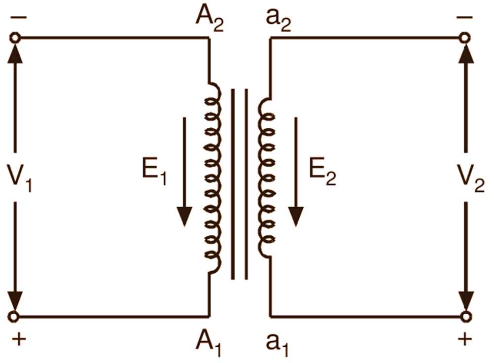
To make the things more clear, consider the two winding single phase transformer shown in Fig. 2. If at any instant, the emf E1 acts from A2 to A1 in the h.v. winding, E2 will act from a2 to al in the l.v. winding i.e. if at any instant A1 is positive and A2 is negative with respect to the applied voltage V1, then the terminal voltage V2 on the secondary l.v. winding will be positive at a1 and negative at a2.

Polarity Test
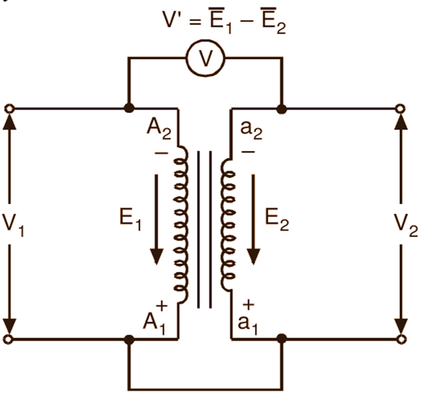
The polarity test is carried out as a routine test on all the transformers newly manufactured. This test is carried out to find the terminals having the same instantaneous polarity, assuming that the terminals are not marked. When viewed from the h.v. side, the terminals are marked A1 and A2, former i.e. A1 being on the extreme right. Terminals A1 and A2 are assumed to have arbitrarily positive and negative instantaneous polarities. Now, A1 is connected to one end of the secondary winding and a voltmeter is connected between A2 and other end of the secondary winding as illustrated in Fig. 3 (a). A voltage of suitable value, say V1 is then applied across the terminals of the h.v. winding. If the voltage $\text{V’}={{\overline{\text{E}}}_{1}}-{{\overline{\text{E}}}_{2}}$ recorded by the voltmeter is less than the applied voltage V1, then the secondary terminal connected to A1 is positive at the same instant and is therefore marked as a1. The L.V. terminal connected to A2 through the voltmeter is then obviously negative and is therefore marked as a2. The transformer under this condition is said to have a subtractive polarity.

(a)

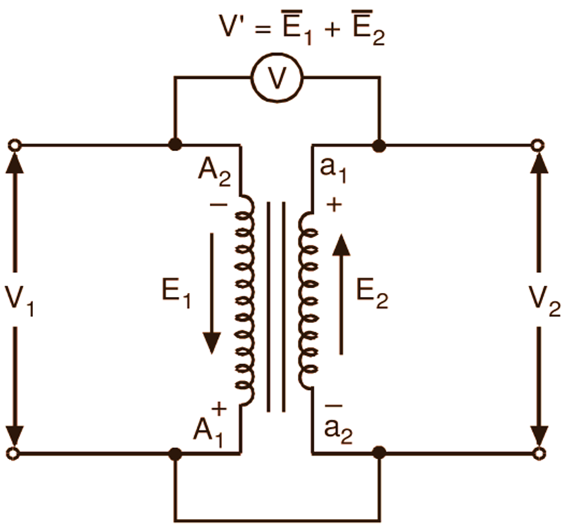
(b)
Fig. 3: Polarity test on a two winding single phase transformer
If the voltmeter reading $\text{V’}={{\overline{\text{E}}}_{1}}+{{\overline{\text{E}}}_{2}}$ is greater than the applied voltage V1, then the secondary terminals connected to A1 and A2 are negative and positive respectively as shown in Fig. 3 (b) and are therefore marked as a2 and a1. The transformer under this condition is said to have additive polarity.
In subtractive polarity, the voltage between A2 and a2 (or A1 and a1) is reduced. The leads connected to these terminals and the two windings are, therefore, not subjected to high voltage stresses. In additive polarity, the two windings and the leads connected to their terminals are subjected to high voltage stresses. Due to this reason, subtractive polarity is preferable to additive polarity.