In this topic, you study PWM Inverter – Definition, Circuit Diagram & Advantages.
PWM Inverter uses PWM (Pulse Width Modulation) technique to control the output voltage of the inverter. This is done to fulfill the AC load requirements. In PWM inverter the controlled output is obtained by adjusting the ON and OFF periods of the inverter components.
Types of PWM (Pulse Width Modulation) Techniques
- Single-Pulse Modulation (SPM).
- Multiple-Pulse Modulation (MPM).
- Sinusoidal-Pulse Modulation (SinPM).
- Phase Displacement Modulation.
All above mentioned PWM techniques have output voltages having different level of harmonic content in it.
Circuit Diagram of the PWM inverter
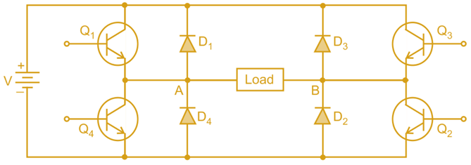
The circuit diagram of the PWM inverter remains the same as which is shown in the following Fig. 1 for all PWM techniques.

Fig. 1: Single phase full bridge inverter
The devices are switched ON and OFF several times within in each half-cycle in order to control the Output voltage which has low harmonic content.
Advantages of using PWM (Pulse Width Modulation) Inverter
- No additional components are required in order to control the output voltage.
- The harmonic of lower order can be eliminated (removed) along with controlling the output voltage.
- Use of PWM Techniques reduces the harmonic content in the output (load) AC voltage.
- PWM inverter have less harmonic content compared to square wave inverter for same fundamental voltage.
- The quality of output voltage is greatly increased in PWM inverters than square wave inverter.
- Voltage control and harmonic reduction can be obtained together within the PWM inverter.
- It is commonly used in adjustable speed A.C motor where we have to feed the motor with variable voltage and variable frequency supply.
- It gives sine wave output for motor loads which is better than sine wave inverters.
- In PWM inverters, the v/f ratio can be kept at constant.