In this topic, you study Parallel Circuit – Definition, Diagram, Formula & Theory.
In a parallel circuit, several resistances are connected across one another, i.e. one terminal of each resistance is connected to a common junction. Similarly, the remaining ends are also joined together to form another junction (Fig. 1). When such a parallel combination of resistances is connected across the supply terminals, full supply voltage is applied across each resistance. The total current delivered by the source has several parallel paths. Each resistance carries its appropriate fraction of the total current just as branches of a river divide the total flow of water between them. For example, the lighting circuit in a house or in a factory consisting of a number of lamps (resistors) joined in parallel is the most familiar example of a parallel circuit.
Current and Voltage Distribution
Fig. 1 shows a parallel circuit consisting of three resistances R1, R2 and R3 connected in parallel across a source of potential difference V volts and drawing a total current of I amperes. Let I1, I2 and I3 be the currents in the resistances R1, R2 and R3 respectively.
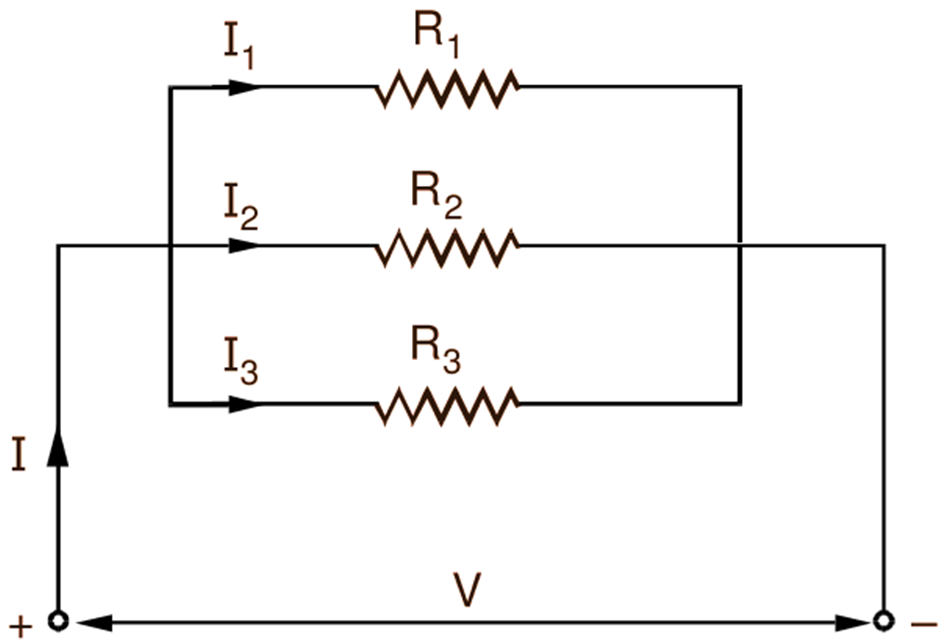
Fig. 1: Parallel combination of resistances
Since the total current from the supply (I) is equal to the sum of the currents flowing through the individual resistances,
\[\text{I}={{\text{I}}_{1}}+\text{ }{{\text{I}}_{2}}+\text{ }{{\text{I}}_{3}}\]
Using Ohm’s Law,
\[\text{I}=\frac{\text{V}}{{{\text{R}}_{1}}}+\frac{\text{V}}{{{\text{R}}_{2}}}+\frac{\text{V}}{{{\text{R}}_{3}}}\]
But,
\[\text{I}=\frac{\text{V}}{\text{R}}\]
where R is the equivalent resistance of the parallel combination. Hence,
\[\frac{\text{V}}{\text{R}}=\frac{\text{V}}{{{\text{R}}_{1}}}+\frac{\text{V}}{{{\text{R}}_{2}}}+\frac{\text{V}}{{{\text{R}}_{3}}}\]
Dividing each term by V, we get
\[\frac{\text{1}}{\text{R}}=\frac{\text{1}}{{{\text{R}}_{1}}}+\frac{\text{1}}{{{\text{R}}_{2}}}+\frac{\text{1}}{{{\text{R}}_{3}}}\]
In general, if the number of resistances connected in parallel is n, then
\[\frac{\text{1}}{\text{R}}=\frac{\text{1}}{{{\text{R}}_{1}}}+\frac{\text{1}}{{{\text{R}}_{2}}}+\frac{\text{1}}{{{\text{R}}_{3}}}+…+\frac{\text{1}}{{{\text{R}}_{\text{n}}}}\]
Thus, summarizing the results, we get
(i) The same potential difference (equal to the supply voltage) is applied across all of the resistances.

(ii) The total current drawn from the supply is equal to the sum Of the currents flowing through the individual resistances.

(iii) The reciprocal of the equivalent resistance of a parallel circuit is equal to the sum of the reciprocals of the individual resistances.
Further, it follows that if n resistors of the same resistance value, say r, are connected in parallel, their equivalent resistance will be given by
\[\text{R}=\frac{\text{r}}{\text{n}}\]