“Resonant converter is a converter which uses an LC resonant circuit, so it is called as resonant converter”.
Resonant converter using high frequency component used in all the four types of converters: AC-DC, AC-AC, DC-AC and DC-DC will be desirable because it will provide tremendous savings in components sizes and weights. As we know that highest switching frequency of converter operation is limited by the losses in the switching devices. Furthermore, the transformers are the primary band-limiting components. Parasitic inductance and capacitance in all components add further limitations.
Need of Resonant Converters
Resonant converter/inverter is defined as a class of converter/ inverter in which the topology consisting of at least one resonant tank circuit as a sub-circuit. A resonant tank is a sub-circuit consisting of at least one inductor and one capacitor. More specially, resonant converters have a resonant tank as a part of the circuit during at least one of the circuit mode in the steady-state converter operation.
In SMPS and in the PWM inverters the switching devices are made to turn-on and turn-off the entire load current at high di/dt. Due to use of high-frequency components used in circuits, the size and weight of converter is to be reduced. Switching frequencies are increased.
Classification of Resonant Converters
Depending on the use of a resonant tank, resonant converters (Fig. 1)are classified as

Fig. 1: Resonant Converters classification
Resonant Link Converters:
These converters consist of AC-DC or DC-AC current voltage source, resonant tank circuit as the link and the multistate sink. Resonant link converters are again classified as:
- Voltage Source Resonant Converter:
(a) Series loaded resonant converter (SLR).
(b) Parallel loaded resonant converter (PLR).
(c) Hybrid resonant converter.
- Current Source Parallel Resonant Converters.
- Class E Resonant Converter.
Resonant Switch Converters:
It consist of resonant elements L and C are utilized primarily in conjunction with the switch to achieve zero/low loss switching, loss-less snubbering add/or soft switching. It is also called as quasi-resonant, pseudo-resonant and resonant transition converters.
Resonant DC-Link Converters:
A resonant tank circuit behaves as a buffer between the DC source and an AC load. The DC link is provided by the inductor of resonant tank circuit. These converters also include zero switching loss topologies.
Resonant AC-Link Converters:
In this, resonant tank circuit provides as a buffer between the DC source and an AC load. The link between the source and load does not have a DC path. These converters also include zero switching loss topologies.
Advantages of Resonant Converter
- Due to high frequency components are used in the circuit, switching losses are reduced and heating Of power devices are also reduced. Therefore the cooling requirement is reduced
- Weight and size is reduced.
- Efficiency of converter is increased because Of power devices operates under zero voltage and zero current condition.
- Noise is reduced.
- RFI/EMI is reduced.
Disadvantages of Resonant Converter
- The power devices will carry higher peak current values.
- In addition to resonant converter circuit and control circuit is required. Therefore it increases the complexity.
Zero Voltage Switching (ZVS) Resonant Converters
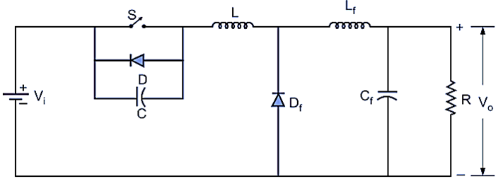
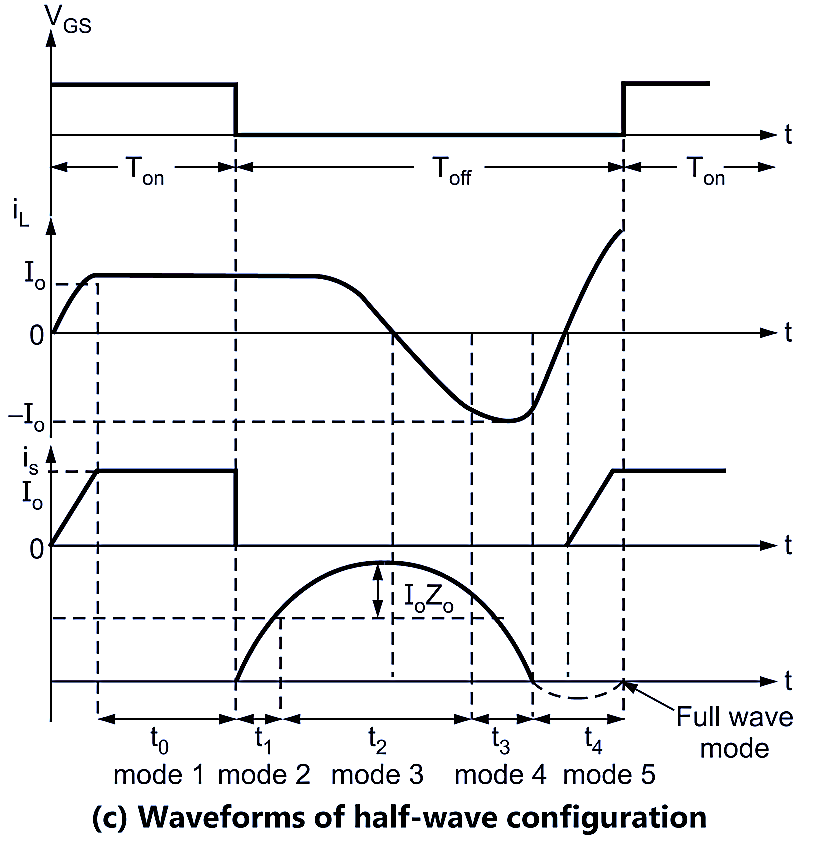
Here the switch turns-on and turns-off at zero voltage. The switch is parallel with the resonant capacitor and in series with the inductor, Fig. 2. Moreover, there are half-wave and full-wave configurations shown in Fig. 3 (a) and Fig. 3 (b).

Fig. 2: ZVS converter.
Normally the filter inductor (Lf) is sufficiently large, therefore I0 is considered to be a constant. During the period (Ton), a gate signal is provided to switch the device, as shown in Fig. 3 (c). The output voltage due to high value of Cf is considered to be constant.


Fig. 3: ZVS converter switch.
During mode 0 or ‘t0’ period, the switch is on and a constant load current (Io) flows through the switching device and both the inductor. When the switching device turns off at the end of t0, the voltage across the device due to C, does not jump to Vi level. Since the switch, device turns-off at zero-voltage conditions, that is why, it is called Zero-Voltage Switching (ZVS). The load current remains constant due to the large value of Lf.
At the beginning of toff period (mode 2), the capacitor C, gets charged at a constant current (Io), when vc exceeds Vi level, DF becomes forward biased and conducts. The inductor current, iL flows in Vi, C, L, I loop. Now L and C resonate in this circuit upto the end of t2 (mode 2). The difference of iL and Io flow in DF (mode 3). In full wave mode, vc becomes negative due to continuation of the resonating current beyond t3. However, in the half wave mode at the beginning of t4, the diode D conducts across the switch and v remains zero during the entire t4 period.